
Auto-Latching Latch Assembly

a latch assembly and latch technology, applied in the direction of building locks, construction fastening devices, construction, etc., can solve the problems of increasing production costs, the latch of the bottom latch assembly cannot be in the latching position, so as to facilitate the description of the invention

Active Publication Date: 2019-01-31
I TEK METAL MFG
View PDF11 Cites 1 Cited by
  • Summary
  • Abstract
  • Description
  • Claims
  • Application Information

AI Technical Summary

Benefits of technology

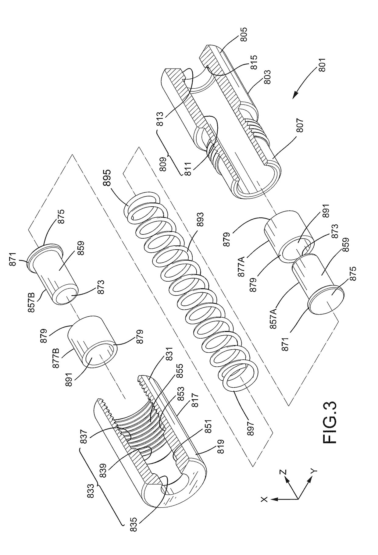
The present invention is a latch assembly that includes a base, a movable member, and a safety device. The movable member is slideably received in the base and includes a first engagement hole, a second engagement hole, and a third engagement hole. The safety device includes a first sleeve and a second sleeve coupled to the first sleeve, with a first stop mounted in the receiving hole of the first sleeve. The latch assembly also includes a limiting member jointly movable with the movable member and a torsion spring. The latch assembly can be used to securely engage and disengage a latch.

Problems solved by technology

However, if the follower door is not in the closed position and the latch of the bottom latch assembly is not in the latching position, the friction between the latch of the bottom latch assembly and the ground adversely affects the pivotal movement of the follower door.
As a result, the bottom latch assembly is so designed that the latch of the bottom latch assembly cannot be in the latching position when the follower door is not in the closed position.
Consequently, the manufacturers have to design two latch assemblies having different structures to respectively serve as the top latch assembly and the bottom latch assembly, resulting in an increase in the production costs.

Method used


Image

  • Auto-Latching Latch Assembly
  • Auto-Latching Latch Assembly
  • Auto-Latching Latch Assembly

Examples


Embodiment Construction

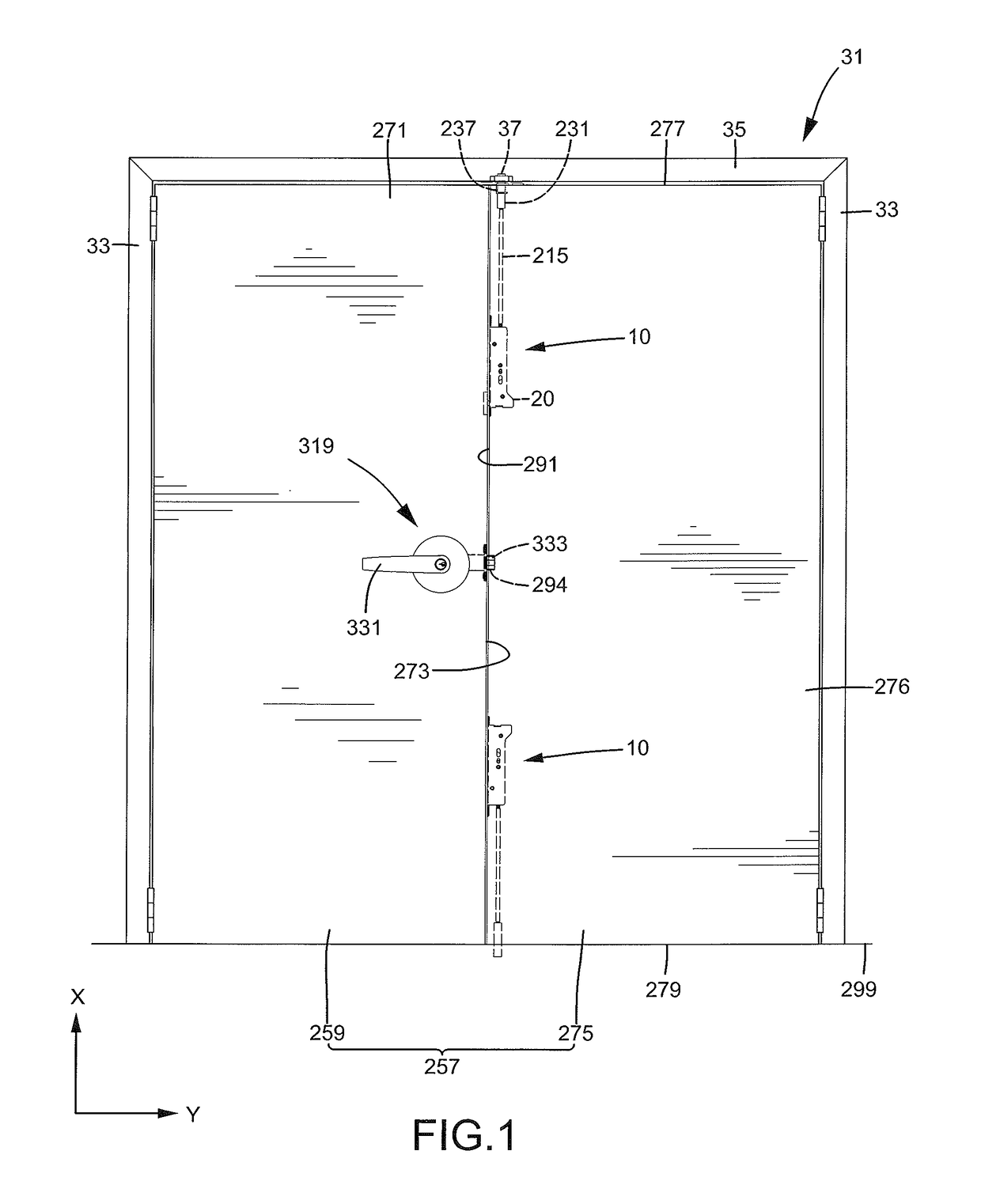
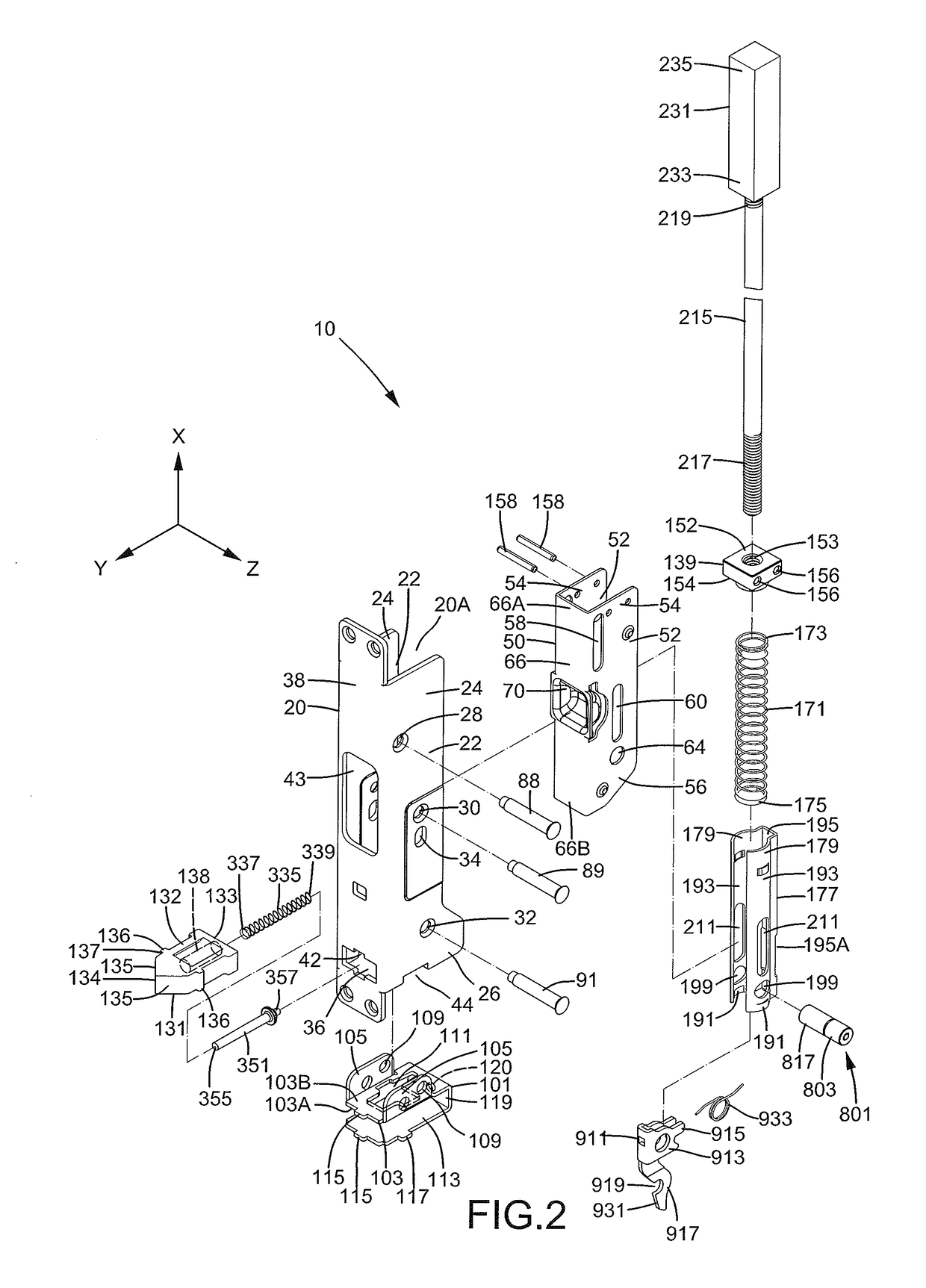
[0027]A latch assembly 10 according to the present invention can be mounted to a double door 257. Double door 257 is mounted to a door frame 31 on a floor or the ground 299. Door frame 31 includes two spaced vertical beams 33 extending along a first axis X perpendicular to ground 299 and a top beam 35 extending between upper ends of vertical beams 33 along a second axis Y perpendicular to first axis X. Top beam 35 includes a groove 37. Double door 257 includes a primary door 259 pivotably mounted to one of vertical beams 33 and a follower door 275 pivotably mounted to the other vertical beam 33. Follower door 275 includes an interior space 293. Primary door 259 includes two sides 271 and an end face 273 extending between sides 271 and extending perpendicularly to ground 299. Follower door 275 includes two sides 276, a top face 277 extending between sides 276 and facing top beam 35, and a bottom face 279 extending between sides 276 and facing ground 299. Top face 277 includes a mount...


PUM


Abstract

An auto-latching latch assembly (10) is mounted to a follower door (275) of a double door (257). The latch assembly (10) includes a latch (231) movable between an unlatching position and a latching position and a movable member (50) jointly movable with the latch (231). A positioning member (911) is jointly pivotable with the movable member (50). When the latch (231) moves to the unlatching position, the positioning member (911) positions the latch (231) in the unlatching position. When the follower door (275) is closed while a primary door (259) of the double door (257) is closed, an actuation latch (131) presses against and releases the positioning member (911) to move the latch (231) to the latching position, reliably locking the follower door (275).

Description

BACKGROUND OF THE INVENTION[0001]The present invention relates to an auto-latching latch assembly and, more particularly, to an auto-latching latch assembly installed in a follower door of a double door for locking when the follower door is closed.[0002]A double door generally includes a primary door and a follower door pivotably mounted to a door frame. A lock is mounted to the primary door and includes a handle on a side of the primary door and a latch on an end face of the primary door. The latch can be retracted into the primary door upon pivotal movement of the handle. A latch assembly mounted to an upper end of the follower door is referred to as a top latch assembly. A latch assembly mounted to a lower end of the follower door is referred to as a bottom latch assembly. Although there are no obstacles for the upper end of the follower door in the pivotal path thereof, the ground is located beneath the lower end of the follower door, such that the structure of the top latch ass...

Claims


Application Information

Patent Timeline
Patent Type & Authority Applications(United States)
IPC IPC(8): E05B17/20E05B63/20E05B15/16E05C7/04
CPCE05B17/2007E05C7/045E05B15/1635E05B63/20E05B17/2038E05B65/104E05C7/06
Inventor LIN, HSI-TING
Owner I TEK METAL MFG
Learn More