Drum Driving Device for Window Shade

Active Publication Date: 2011-01-20
ZHU XIANG RONG
View PDF6 Cites 8 Cited by
  • Summary
  • Abstract
  • Description
  • Claims
  • Application Information

AI Technical Summary

Benefits of technology

[0001]The present invention relates to a drum driving device for a window shade and, more particularly, to a drum driving device for a window shade that is simple in structure and reliable in operation.

Problems solved by technology

However, friction exists between the sliding block and the inclined groove.
Frequent use causes wear to the sliding block and the inclined groove.
Thus, the inclined groove is liable to wear, causing non-smooth movement of the sliding block and causing malfunction of the clutch device.
Further, the clutch device is complicated and, thus, has high manufacturing costs.

Method used


Image

  • Drum Driving Device for Window Shade
  • Drum Driving Device for Window Shade

Examples


Embodiment Construction

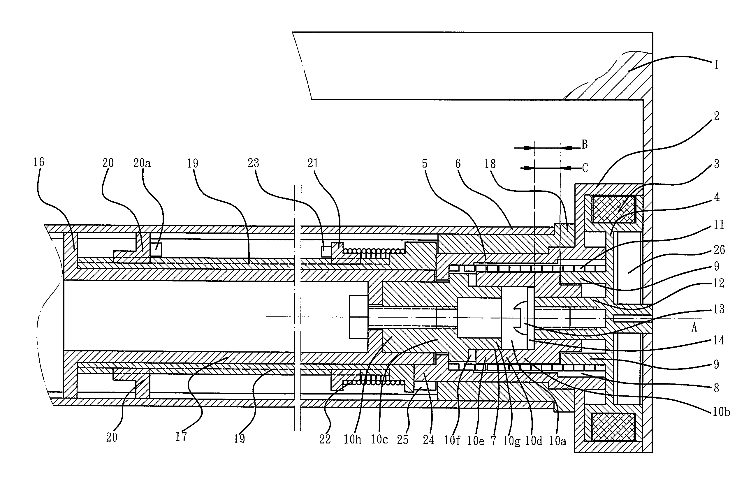
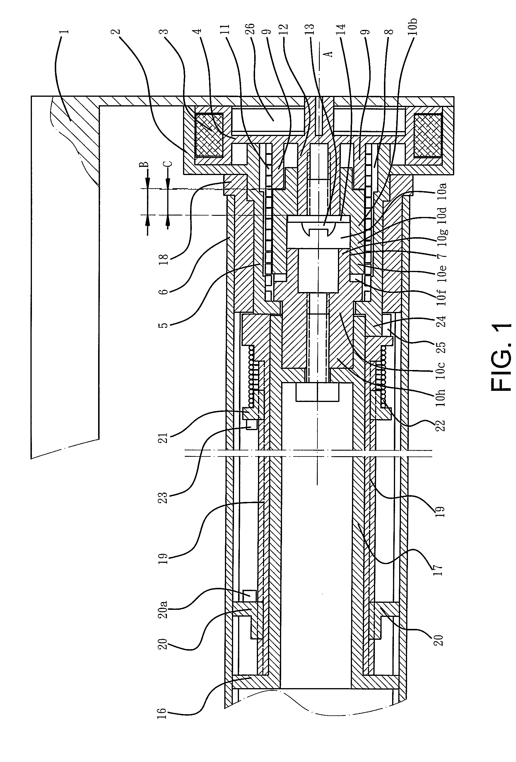
[0011]With reference to FIG. 1, a drum driving device for a window shade according to the preferred teachings of the present invention generally includes a housing 2 fixed to a frame 1 of the window shade, a cord pulley 4 rotatably received in housing 2 and having a cord 3 wound around cord pulley 4, a drum 6 rotatably mounted by a connecting member 18 to a drum shaft 5 received in housing 2, and a single-direction clutch device 7 mounted between drum 6 and cord pulley 4. A return spring 26 is mounted between cord pulley 4 and housing 2.

[0012]Clutch device 7 includes a chamber 8 defined in housing 12 and coaxial to an axis A of housing 2, a driving shaft 9 coaxially mounted to cord pulley 4, a transmission shaft 10 mounted in chamber 8, and a driving spring 11 mounted to an inner periphery of chamber 8 and around driving shaft 9 and transmission shaft 10 in chamber 8. Transmission shaft 10 has an outer diameter not larger than that of transmission shaft 9. Preferably, the outer diam...


PUM


Abstract

A drum driving device for a window shade includes a housing fixed to a frame of the window shade. A cord pulley is rotatably received in the housing. A drum is rotatably mounted to a drum shaft received in the housing A single-direction clutch device is mounted between the drum and the cord pulley. The clutch device includes a chamber defined in the housing. A driving shaft is coaxially mounted to the cord pulley. A transmission shaft is mounted in the chamber. A driving spring is mounted to an inner periphery of the chamber and around the driving shaft and the transmission shaft in the chamber. The transmission shaft has an outer diameter not larger than that of the transmission shaft. The driving spring is in tight contact with the driving shaft and the inner periphery of the chamber. The transmission shaft is extended out of the chamber and connected to the drum.

Description

BACKGROUND OF THE INVENTION[0001]The present invention relates to a drum driving device for a window shade and, more particularly, to a drum driving device for a window shade that is simple in structure and reliable in operation.[0002]A drum driving device disclosed in China Utility Model No. 200820044961.2 includes a single direction clutch device mounted between a drum and a cord pulley. The clutch device is comprised of a shaft coaxially mounted to the drum for driving the drum to rotate and a slideable rotary seat coaxial to the shaft for clutching purposes. An end face of the shaft coupled to the rotary seat includes teeth for single-direction coupling. A housing includes an axial hole coaxial to the drum. The shaft has a clutch shaft section to which an end of the rotary seat is engaged. The engaging location of the clutch shaft section and the end of the rotary seat is in the axial hole. The other end of the rotary seat is located in a socket in side of the cord pulley and in...

Claims


Application Information

Patent Timeline
IPC IPC(8): E06B9/60E06B9/78
CPCE06B2009/785E06B9/78E06B9/322E06B9/42E06B9/56
Inventor ZHU, XIANG-RONG
Owner ZHU XIANG RONG
Why Eureka
Try Eureka