Wireless Remote Control System and Methods for Monitoring and Controlling Illuminating Devices

a technology of illuminating devices and remote control systems, which is applied in the direction of lighting apparatus, instruments, light sources, etc., can solve the problems of illuminating device malfunction, wasting energy, and unable to provide the required illumination, etc., to facilitate the description of the invention

Inactive Publication Date: 2011-03-31
LIAO YUN CHANG
View PDF7 Cites 9 Cited by
  • Summary
  • Abstract
  • Description
  • Claims
  • Application Information

AI Technical Summary

Benefits of technology

[0010]FIG. 3 shows a schematic block diagram of the illuminating device of FIG. 2, a control center, and a network device according to the preferred teachings of the present invention.
[0011]FIG. 4 shows a control panel of the control center according to the preferred teachings of the present invention.
[0012]All figures are drawn for ease of explanation of the basic teachings of the present invention only; the extensions of the figures with respect to number, position, relationship, and dimensions of the parts to form the preferred embodiments will be explained or will be within the skill of the art after the following teachings of the present invention have been read and understood. Further, the exact dimensions and dimensional proportions to conform to specific force, weight, strength, and similar requirements will likewise be within the skill of the art after the following teachings of the present invention have been read and understood.
[0013]Where used in the various figures of the drawings, the same numerals designate the same or similar parts. Furthermore, when the terms “first”, “second”, “last”, and similar terms are used herein, it should be understood that these terms have reference only to the structure shown in the drawings as it would appear to a person viewing the drawings and are utilized only to facilitate describing the invention.

Problems solved by technology

However, these systems only offer detection of opening, closing, and malfunction of the illuminating devices.
The illuminating devices are in a full-load state by increasing the voltage or current in a period of time after they are turned on, which is a waste of energy, because the illuminating devices do not have to always be in the full-load state due to various reasons.
Furthermore, the illuminating devices could not provide the required illumination when they are damaged or deteriorate.
Further, the illuminating devices often provide light beams of a certain color, which is not always suitable in various situations.

Method used


Image

  • Wireless Remote Control System and Methods for Monitoring and Controlling Illuminating Devices
  • Wireless Remote Control System and Methods for Monitoring and Controlling Illuminating Devices
  • Wireless Remote Control System and Methods for Monitoring and Controlling Illuminating Devices

Examples


Embodiment Construction

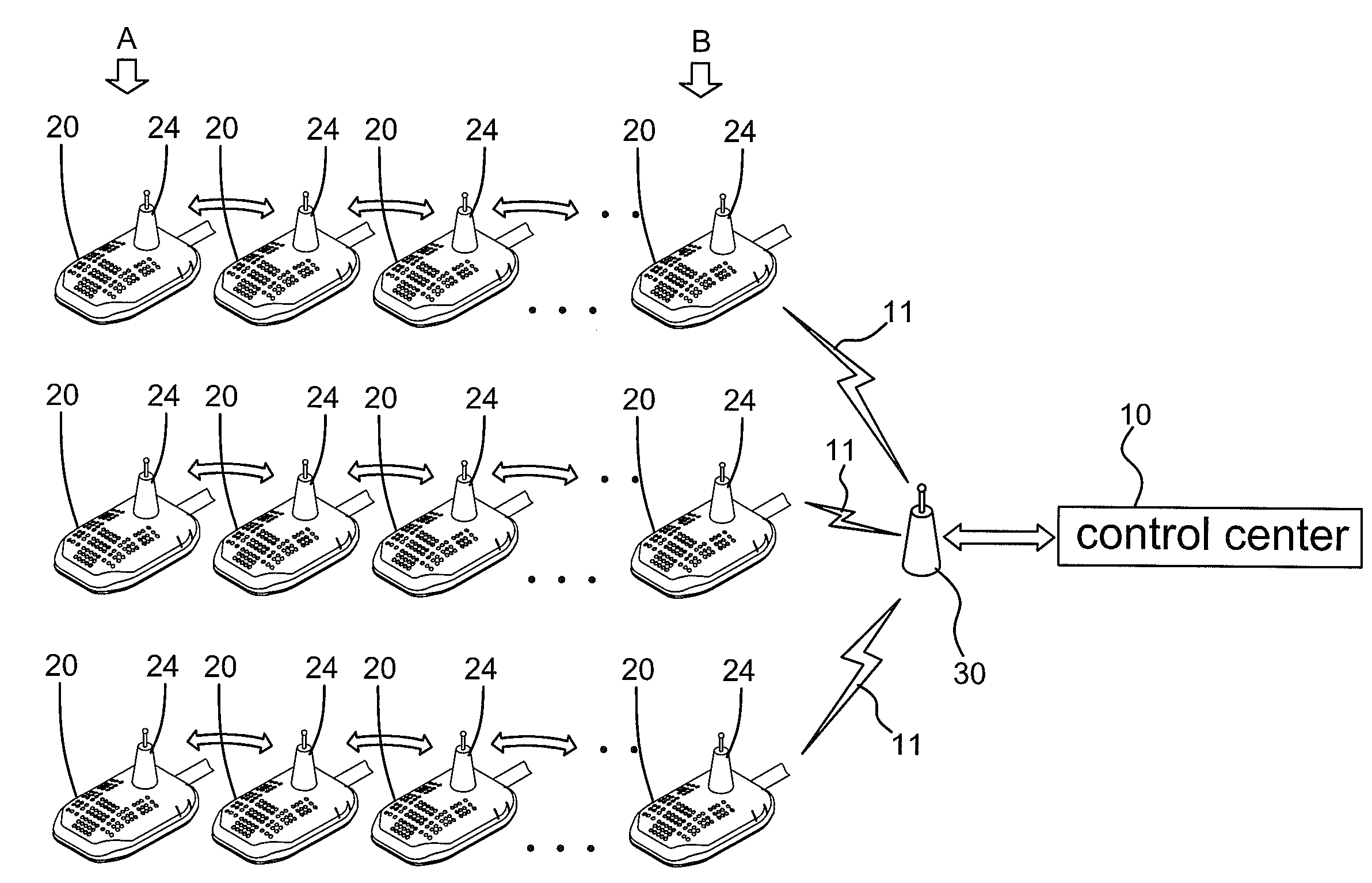
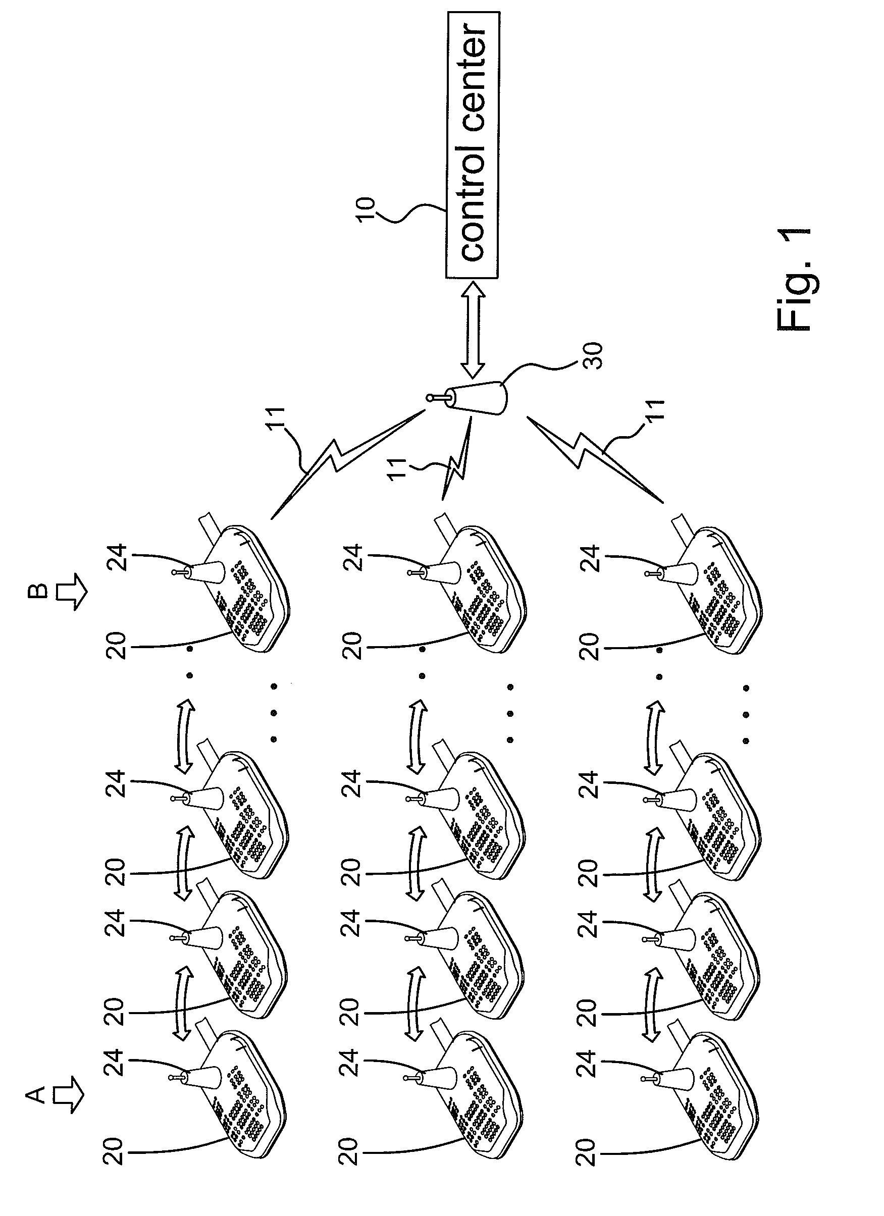
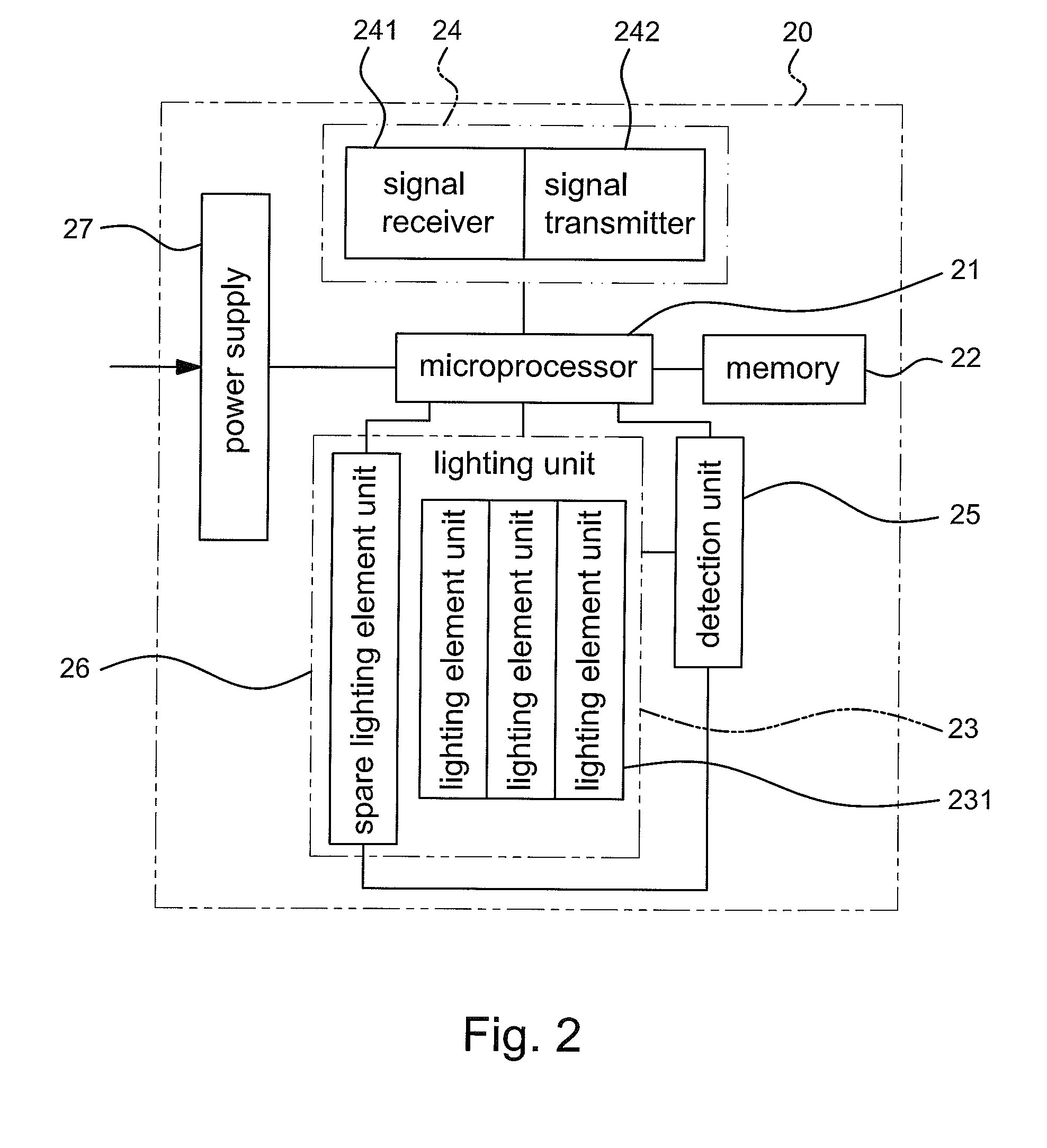
[0014]A wireless remote control system according to the preferred teachings of the present invention is shown in the drawings and generally includes a control center 10, a plurality of groups of illuminating devices 20, and a network device 30 providing interconnection between control center 10 and illuminating devices 20. Each illuminating device 20 includes a microprocessor 21, a memory 22 electrically connected to microprocessor 21, a lighting unit 23 electrically connected to and controlled by processor 21, a wireless transmitting unit 24 electrically connected to microprocessor 21, a detection unit 25 electrically connected to lighting unit 23 and microprocessor 21, and a power supply 27 electrically connected to microprocessor 21 and an external power system. Power supply 27 supplies lighting unit 23 with electricity for lighting purposes.

[0015]Memory 22 of each illuminating device 20 includes an identification number indicative of at least one of a location and a serial numbe...


PUM


Abstract

A system includes first and second illuminating devices respectively having different first and second identification numbers indicative of locations and/or serial numbers of the illuminating devices. A parameter of one of voltage, temperature, resistance, and power of a lighting unit of each illuminating device is detected. The parameter and the identification number of each illuminating are encoded into a packet. The second illuminating device receives the packet of the first illuminating device and sends the packets of the first and second illuminating devices to a control center. The control center decodes the packets and judges operational states of the illuminating devices based on the parameters detected. A control signal is sent by the control center to open or close or control brightness of at least one of the illuminating devices when at least one of the illuminated devices is judged as operating abnormally after judging the parameters detected.

Description

BACKGROUND OF THE INVENTION[0001]The present invention relates to a wireless remote control system and methods for monitoring and controlling illuminating devices, more particularly, to a wireless remote control system and methods for monitoring and controlling illuminating devices such as road lamps or the like utilized in public areas such as roads, parks, etc.[0002]Public areas such as roads and parks are generally provided with illuminating device such as road lamps to provide illumination in the night or in the rainy or foggy days. Systems for detecting operation of the illuminating devices by wire or wireless connection have been utilized to save labor and to quickly find out problems of the illuminating devices. These systems generally include sensors for detecting a parameter such as voltage, electric current, circuit, brightness, or temperature of the illuminating devices, and sending a signal indicative of the parameter to a control center including build-in programs to ju...

Claims


Application Information

Patent Timeline
Patent Type & Authority Applications(United States)
IPC IPC(8): H05B37/02
CPCH05B37/034H05B37/0272H05B47/22H05B47/19
Inventor LIAO, YUN-CHANG
Owner LIAO YUN CHANG
Why Eureka
Try Eureka