A multirotor wind turbine
a multi-rotor wind turbine and wind power technology, applied in the direction of wind power generation, motors, passive/reactive control, etc., can solve the problems of sudden ‘flipping’ of self-yawing mechanisms and the introduction of loads in the load carrying structur
Active Publication Date: 2019-02-14
VESTAS WIND SYST AS
View PDF0 Cites 5 Cited by
- Summary
- Abstract
- Description
- Claims
- Application Information
AI Technical Summary
Benefits of technology
The invention aims to develop a wind turbine with multiple rotors that can successfully yaw in wind conditions, ensuring reliability and efficiency.
Problems solved by technology
When the wind acts on energy generating units mounted in this manner, thrust forces will be created, which will in turn cause loads to be introduced in the load carrying structure, and possibly at connection points between the load carrying structure and the tower structure.
However, under certain conditions, e.g. under turbulent wind conditions, there is a risk that these self-yawing mechanisms suddenly ‘flip’, i.e. rotate the entire load carrying structure approximately 180°, and the load carrying structure is subsequently slowly rotated into a correct orientation.
Method used
View moreImage
Smart ImageViewing Examples
Examples
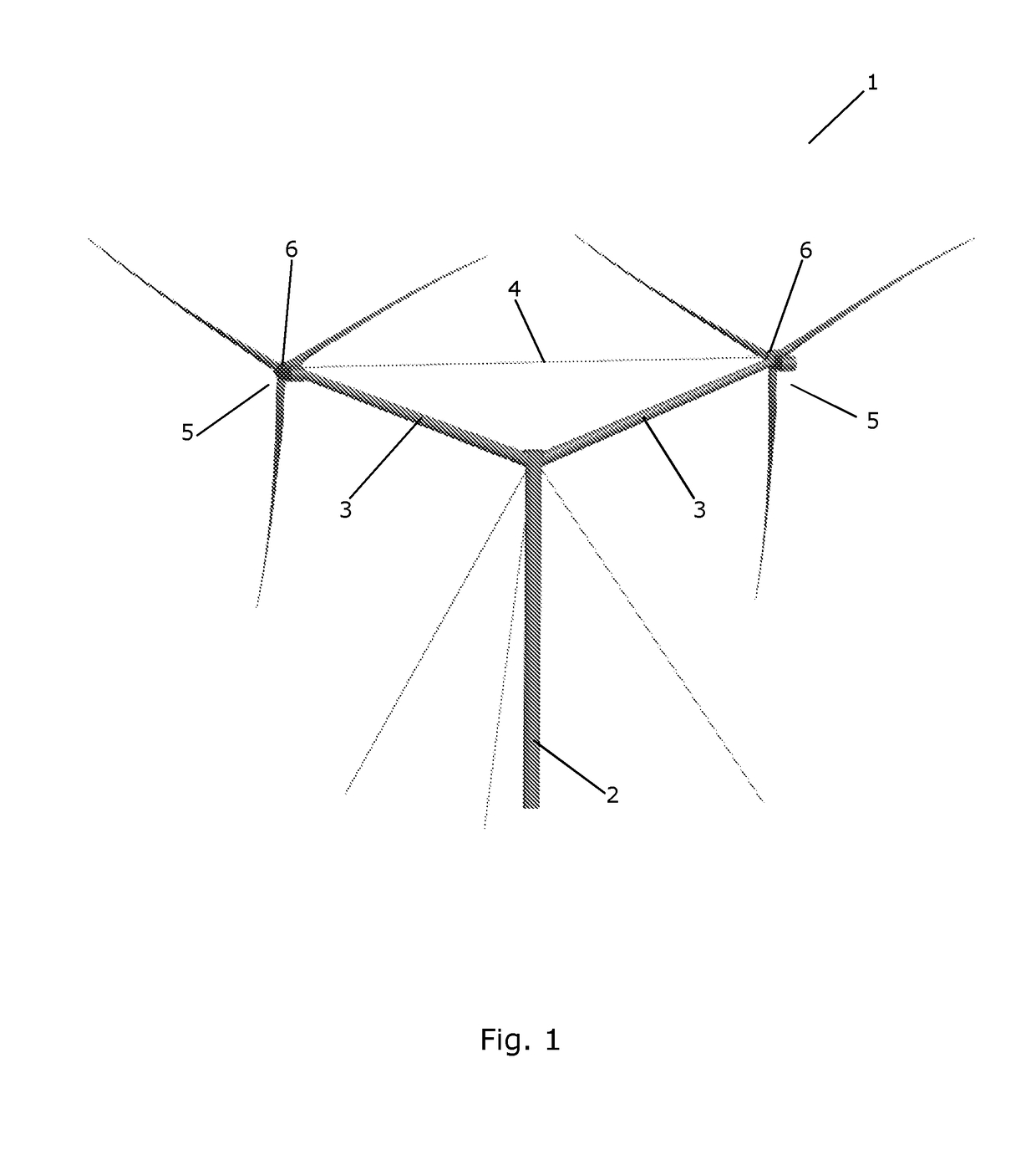
first embodiment
[0060]FIG. 1 is a perspective view of a multirotor wind turbine according to the invention,
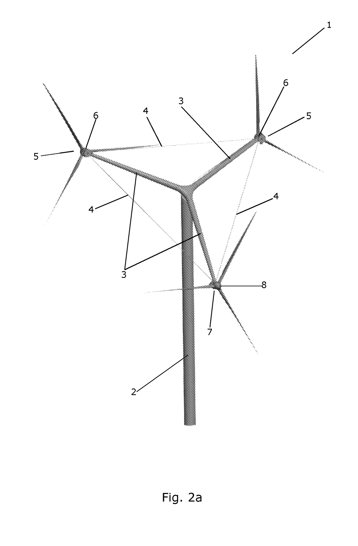
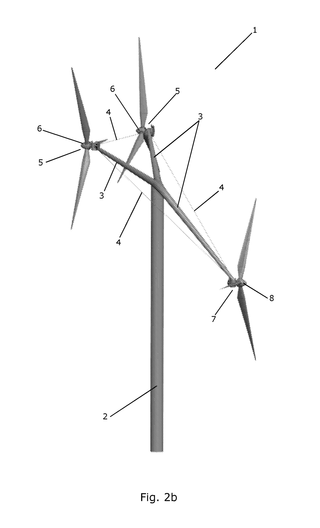
second embodiment
[0061]FIGS. 2a and 2b are perspective views of a multirotor wind turbine according to the invention,
third embodiment
[0062]FIGS. 3a and 3b are perspective views of a multirotor wind turbine according to the invention,
Login to View More PUM
 Abstract
A multirotor wind turbine (1) comprising a tower structure (2) and at least one load carrying structure (3, 4), each load carrying structure (3, 4) being arranged for carrying two or more energy generating units (5, 7) comprising a rotor (6, 8). At least two of the rotors are upwind or downwind rotors (6), the energy generating units (5) comprising upwind or downwind rotors (6) being arranged with their centres of gravity at a first distance behind the tower structure (2) along a direction of the incoming wind, substantially at the same vertical level, and at opposite sides of the tower structure (2) at substantially the same second distance to the tower structure (2) along a direction substantially perpendicular to the direction of the incoming wind. The multirotor wind turbine (1) is self-yawing, even under turbulent wind conditions.
Description
FIELD OF THE INVENTION[0001]The present invention relates to a multirotor wind turbine, i.e. a wind turbine comprising two or more energy generating units arranged on a common tower structure, each energy generating unit comprising a rotor. The multirotor wind turbine according to the invention is capable of reliable self-yawing, even under turbulent wind conditions. Furthermore, according to some of the embodiments of the invention, the multirotor wind turbine provides torque equalization.BACKGROUND OF THE INVENTION[0002]Wind turbines normally comprise one or more energy generating units, each energy generating unit comprising a rotor comprising a hub carrying one or more wind turbine blades. The wind acts on the wind turbine blades, thereby causing the hub to rotate. The rotational movements of the hub are transferred to a generator, either via a gear arrangement or directly, in the case that the wind turbine is of a so-called direct drive type. In the generator, electrical energy...
Claims
Login to View More Application Information
Patent Timeline
 IPC IPC(8): F03D1/02F03D7/02F03D13/20
CPCF03D1/02F03D7/0204F03D13/20F05B2240/2213F05B2240/2211F05B2270/402Y02E10/72Y02E10/728
Inventor ANDERSEN, PETER BJORNSCHOMACKER, JONAS LERCHEGUPTA, ANURAGKUDSK, HENRIK
Owner VESTAS WIND SYST AS
Features
- R&D
- Intellectual Property
- Life Sciences
- Materials
- Tech Scout
- Unparalleled Data Quality
- Higher Quality Content
- 60% Fewer Hallucinations
Learn More Browse by: Latest US Patents, China's latest patents, Technical Efficacy Thesaurus, Application Domain, Technology Topic, Popular Technical Reports.
© 2025 PatSnap. All rights reserved.Legal|Privacy policy|Modern Slavery Act Transparency Statement|Sitemap|About US| Contact US: help@patsnap.com


