Illuminated dental mirror

a technology of dental mirrors and mirrors, applied in the field of dental mirrors, can solve the problems of poor illumination, cave-like mouth, and user's hands affecting the effect of lighting sources,

Inactive Publication Date: 2019-03-07
RAYDENT CORP
View PDF9 Cites 6 Cited by
  • Summary
  • Abstract
  • Description
  • Claims
  • Application Information

AI Technical Summary

Benefits of technology

[0005]According to another aspect of the present invention, a dental mirror includes an elongated body that has a handle portion and a tip portion with a hollow interior chamber. A light source is disposed within the elongated body and is operable to emit light toward a distal end of the tip portion. A lens member is coupled with the light source and is disposed within the interior chamber of the tip portion. The lens member is configured to transmit light longitudinally along the elongated body from the light source toward the distal end of the tip portion. A deflector is disposed at the interior chamber of the tip portion and is configured to redirect light transmitted from the le...

Problems solved by technology

One may consider the mouth to be cave-like and typically poorly illuminated.
Th...

Method used


Image

  • Illuminated dental mirror
  • Illuminated dental mirror
  • Illuminated dental mirror

Examples


Embodiment Construction

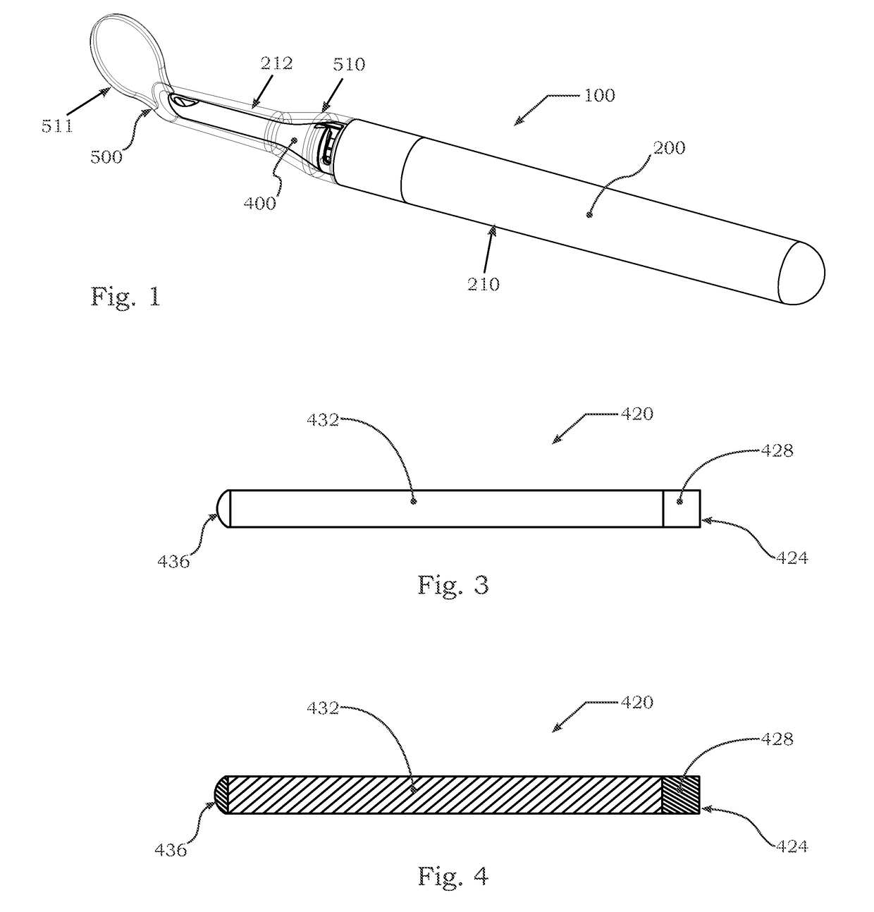
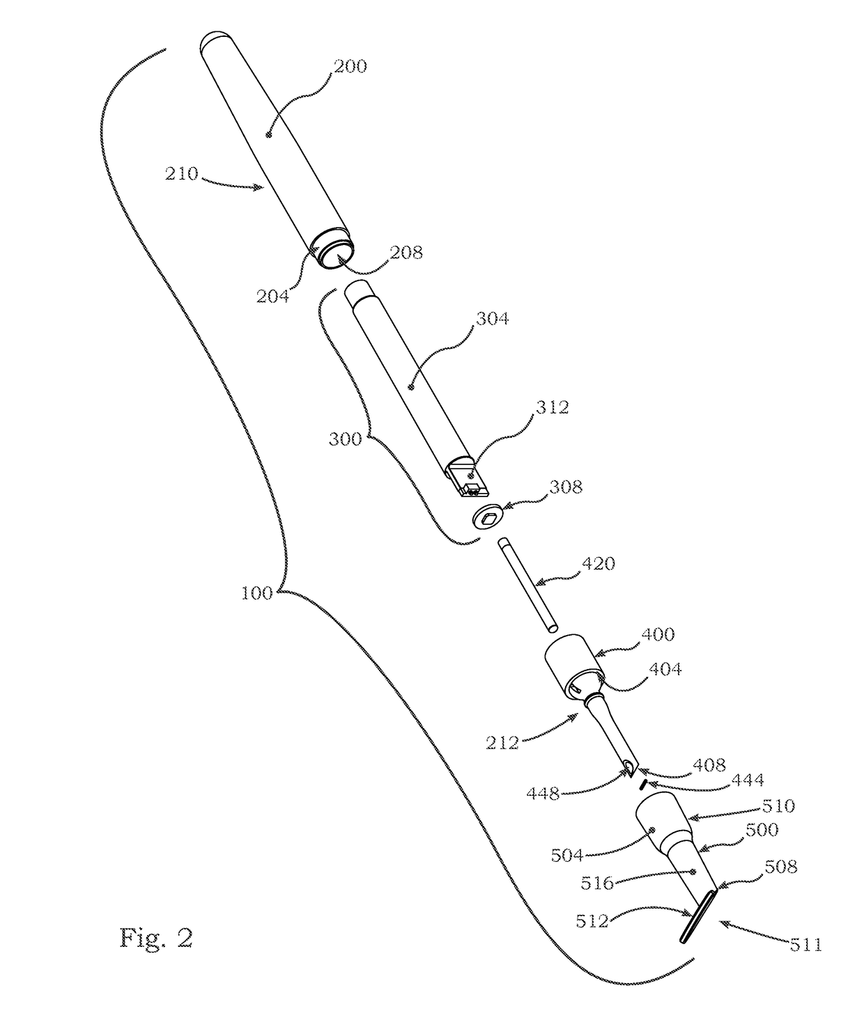
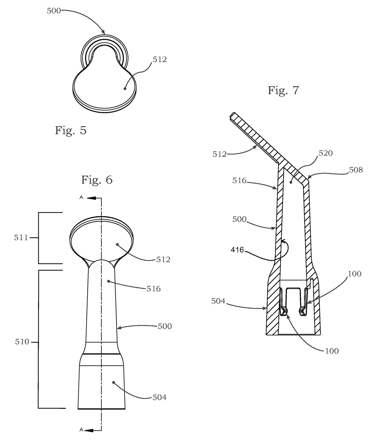
[0034]Referring now to the drawings and the illustrative embodiments depicted therein, an illuminated dental mirror 100 includes an elongated body 200 that has a handle portion 210 and a tip portion 212, such as shown as a cap 400 in FIGS. 1-19. A light source 300 is disposed within the elongated body 200 and is operable to emit light longitudinally along the elongated body 200 to a deflector 444, such as a mirror or polished surface or the like, disposed at an interior chamber of the tip portion 212. The deflector 444 is configured to redirect light laterally out of the tip portion 212 of the elongated body 200. A disposable mirror head 500 is removably attached over the tip portion 212. The mirror head 500 includes a base portion 510 and a mirror portion 511. The base portion of the mirror head 500 has a translucent material configured to transmit the light redirected by the deflector 444 to a desired area outside the mirror head 500. The mirror portion 511 extends at an angle fro...


PUM


Abstract

An illuminated dental mirror includes an elongated body that has a handle portion and a tip portion. A light source is disposed within the elongated body and is operable to emit light longitudinally along the elongated body to a deflector disposed at an interior chamber of the tip portion. The deflector is configured to redirect light laterally out of the tip portion of the elongated body. A disposable mirror head is removably attached over the tip portion. The mirror head includes a base portion and a mirror portion. The base portion of the mirror head has a translucent material configured to transmit the light redirected by the deflector to a desired area outside the mirror head. The mirror portion that extends at an angle from the base portion and comprises a mirror that is configured for a user to view the desired area illuminated by the light source.

Description

FIELD OF THE INVENTION[0001]The invention relates to dentistry and more specifically to a hand held dental mirror, commonly known for dental inspection.BACKGROUND OF THE INVENTION[0002]One may consider the mouth to be cave-like and typically poorly illuminated. Various lighting equipment is known to focus or project light from a source toward a selected object. This lighting equipment may be mounted on a stand, an arm, or another mechanism having a similar function for positioning by a user. Lighting equipment may alternatively be mounted on a user's head such that illumination may be maneuvered by the user manipulating his head. These lighting sources may easily be blocked by the user's hands and the like, however.SUMMARY OF THE INVENTION[0003]The present invention provides an illuminated dental mirror that may comprise a handle with a light source in a body of the handle. A light rod or lens may direct light from the light source to a terminal end of a tip of the handle body. The ...

Claims


Application Information

Patent Timeline
IPC IPC(8): A61B1/247A61B1/07A61B1/00A61B1/06
CPCA61B1/247A61B1/07A61B1/0669A61B1/00105A61B1/00103A61B1/00096A61B1/00101A61B1/00108A61B1/0615
Inventor BOURGET, PAUL L.BRUNT, JR., HAROLD W.MCCONNELL, DONALD P.PHILLIPS, ROBERT R.SOBECKI, JUSTIN E.IPPEL, DAVID J.ZATZKE, BRIAN S.
Owner RAYDENT CORP
Why Eureka
Try Eureka