Knit Prosthetic Liner Textile With Differentiated Knit Fabric Exterior

a technology of knit fabric and prosthetic legs, applied in the field of liners, can solve the problems of delay between the time of residual limb movement, amputees will find it difficult to flex the knee, and high construction cost, and achieve the effect of preventing “pistoning” and lowering longitudinal stretch

Active Publication Date: 2019-03-07
ALPS SOUTH EURO
View PDF3 Cites 2 Cited by
  • Summary
  • Abstract
  • Description
  • Claims
  • Application Information

AI Technical Summary

Benefits of technology

[0016]Specifically, the present invention relates to a prosthetic liner having a lower longitudinal stretch in the distal region than in either the proximal or optional intermediate region. The distal region may stretch anywhere from 0-30% vertically and 10-200% horizontally as compared to the proximal region's vertical stretch of 55-125% and 100-175% horizontally. The stretch of the liner at various pressure sensitive regions of a residual limb can also be lowered or heightened depending on the area. A variety of stitches may be used at the distal end to implement this lowered longitudinal stretch. Preferably, the liner is made of a stretchable material. The liner also has an interior layer of elastomer gel. The design of this prosthetic liner is primarily to prevent the “pistoning” of the amputee's residual limb within the liner and for comfort over pressure-sensitive areas of the residual limb.

Problems solved by technology

This means that every time the amputee attempted to move his / her leg, there would be a delay between when the residual limb moved and when the prosthesis moved.
On the other hand, if there is no longitudinal elongation then the amputee will find it difficult to flex the knee.
However, this construction is expensive to construct due to the fact that the additional steps of applying adhesive to the interior of the exterior fabric, applying the reinforcing matrix to the adhesive layer, and curing of the adhesive are required.

Method used


Image

  • Knit Prosthetic Liner Textile With Differentiated Knit Fabric Exterior
  • Knit Prosthetic Liner Textile With Differentiated Knit Fabric Exterior
  • Knit Prosthetic Liner Textile With Differentiated Knit Fabric Exterior

Examples


Embodiment Construction

[0026]The following description is of the best mode presently contemplated for carrying out the invention. This description is not to be taken in a limiting sense, but is made merely for the purpose of describing one or more preferred embodiments of the invention. The scope of the invention should be determined with reference to the claims.

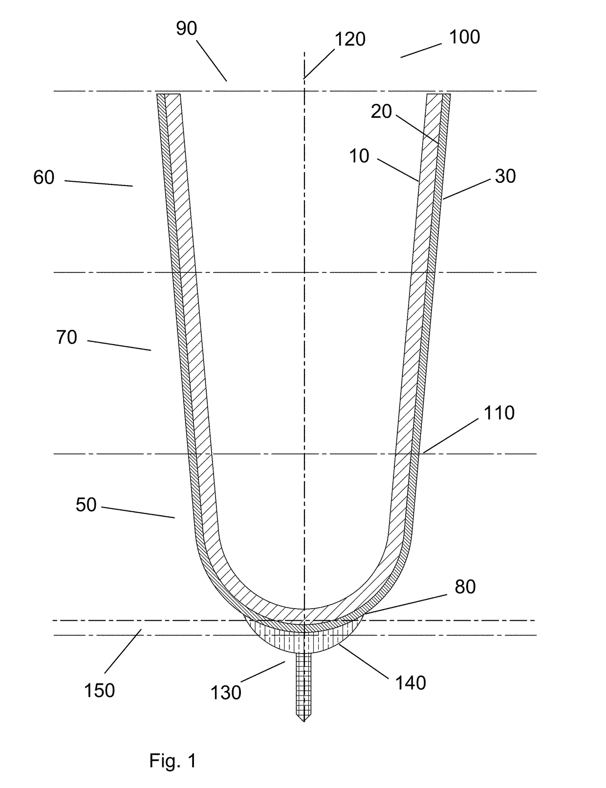
[0027]The present invention relates to a liner 100 for use with prosthetic devices. As shown in FIG. 1, the liner 100 for use with a prosthetic assembly comprises a plurality of types of stitching. The liner 100 comprises a distal region 50, proximal region 60, and an optional intermediate region 70. In one embodiment, the distal region 50 that comprises the distal end 80 of the liner is constructed with a reduced vertical stretch when compared to the upper region 60 of the liner. Preferably, the distal region 80 has a vertical stretch of 0-30% and a horizontal stretch of 10-200% as compared to the proximal region 60, which preferably has a vertic...


PUM


Abstract

A prosthetic liner for use with a prosthetic assembly that acts as the interface between the residual limb of an amputee and the socket assembly. The prosthetic liner comprises an outer textile with variable stretch characteristics due to the knit construction and stitching and an interior gel layer. The distal region of the liner textile has less stretch than does the intermediate region or proximal region and is stitched together to form a unitary liner. The liner advantageously minimizes a condition referred to as “pistoning” wherein the distal most portion of the residual limb ascends and descends in the lower portion of the socket creating an unhealthy condition for the residual limb.

Description

CROSS-REFERENCE TO RELATED APPLICATIONS[0001]This application claims priority to pending provisional application No. 62 / 554,102 filed Sep. 5, 2017, the disclosure of which is hereby incorporated by reference herein.BACKGROUND OF THE INVENTIONField of the Invention[0002]This invention relates to liners for use in a prosthetic assembly. More particularly, the described invention relates to liners having a particular stitching such that the distal end of the liner has less stretch than the proximal end of the liner so as to reduce pistoning.Description of the Background Art[0003]Prosthetic liners have been in use since the 1970's, mostly custom made, and made of various materials. Silicone liners, without a fabric cover, were developed in the late 1980s and became widely used as of the 1990s. During that time, the first versions of fabric covered liners were developed.[0004]The liners disclosed in U.S. Pat. Nos. 5,443,525, 5,507,234, 5,728,168, 6,544,292, and 6,764,631 each represent a...

Claims


Application Information

Patent Timeline
Patent Type & Authority Applications(United States)
IPC IPC(8): A61F2/78A61F2/80
CPCA61F2/7812A61F2/80A61F2002/608A61F2002/501A61F2002/7818A61F2002/7875A61F2/5044
Inventor LAGHI, ALDOVINT, NATHANIEL
Owner ALPS SOUTH EURO
Why Eureka
Try Eureka