

Obstacle course with illuminated ball pit
a technology of obstacle course and ball pit, which is applied in the field of obstacle course, can solve the problems of user falling off the obstacle and falling user lands in the area below the obstacl
- Summary
- Abstract
- Description
- Claims
- Application Information
AI Technical Summary
Benefits of technology
Problems solved by technology
Method used
Image

Examples
Embodiment Construction
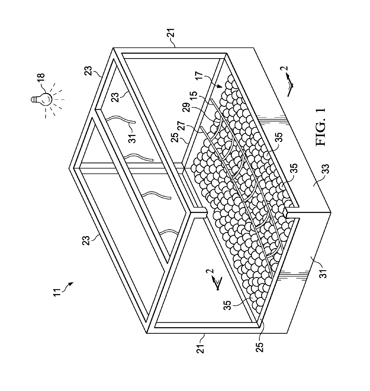
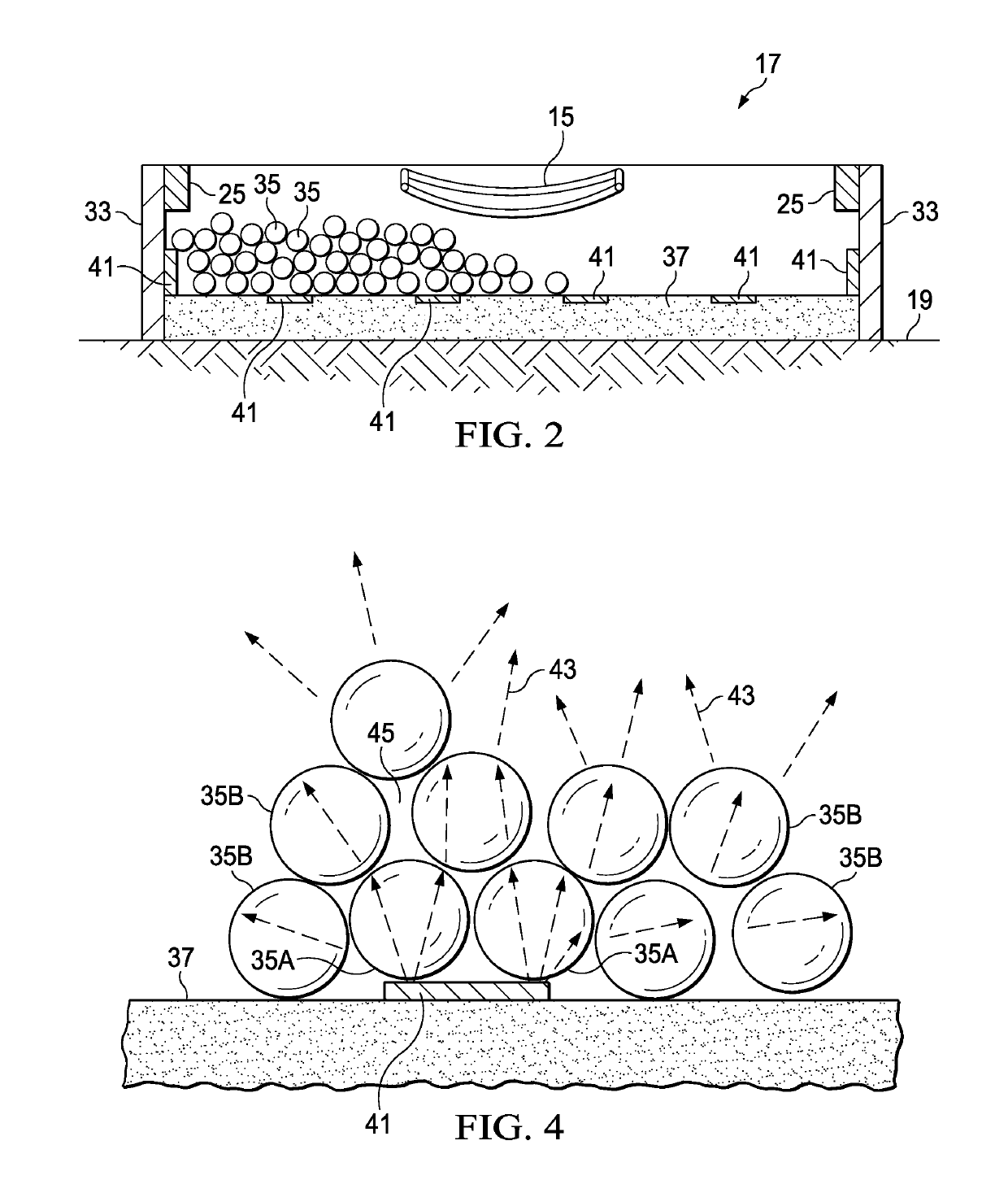
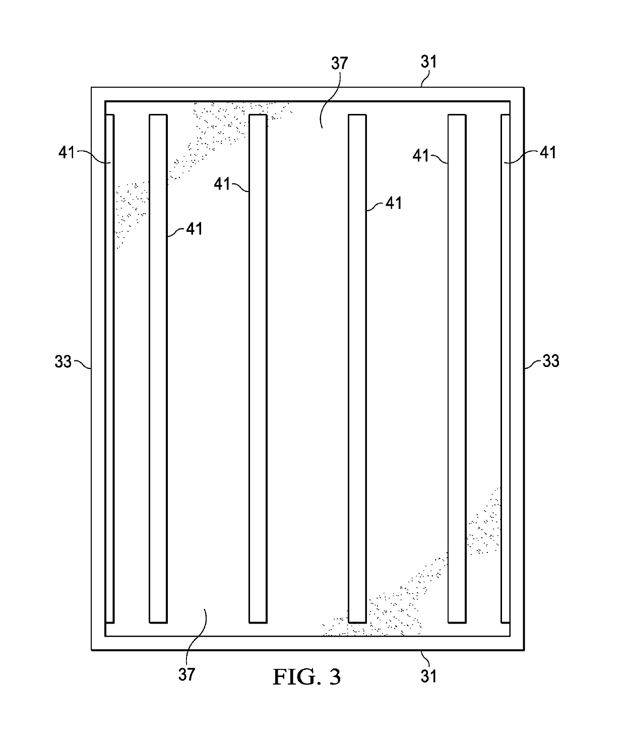
[0022]The obstacle course has one or more obstacles that traverse spaces or spans of distance. At least, one of the obstacles is provided with a cushioned landing area that is both comfortable to land on and aesthetically pleasing. The landing area is covered with a ball pit. A user landing on the landing area lands in relative comfort on the balls. The balls are transparent or translucent. Lighting is provided so as to illuminate the balls, and the landing area, thus adding to the visual aesthetics of the obstacle. This lighting is in addition to any ambient lighting over the obstacle course. In addition, a cushioning layer is provided beneath the balls to further soften landings, and in particular landings where an arm or a leg penetrates into the balls.
[0023]The obstacle course has plural obstacle units. Each obstacle unit includes an obstacle and supporting structure for the obstacle. In addition, each obstacle unit typically includes something to allow for a user to fall safely...
PUM
 Abstract
Description
Claims
Application Information