Camera mounting system

a technology for mounting systems and cameras, applied in the direction of screws, cycle equipment, instruments, etc., can solve the problems of damage to the mounting points, high shock and or both, and achieve the effect of preventing or minimizing the vibration of the action camera, minimizing the movement of the action camera mount, and being sufficiently robust to be tightened

Active Publication Date: 2019-05-02
IWON
View PDF2 Cites 2 Cited by
  • Summary
  • Abstract
  • Description
  • Claims
  • Application Information

AI Technical Summary

Benefits of technology

[0005]What is needed is a mounting system and associated hardware that permits a user to securely mount an action camera to various structures in a manner that prevents or minimizes vibration of the action camera. An embodiment of the inventive device may comprise one or more robust joint structures which allow adjustments across several axes of adjustment, so as to permit a user to align the action camera such that a desired image or video may be captured. Also needed is a fastener that is sufficiently robust to be tightened in a way which minimizes the movement of the action camera mount. An embodiment of such a fastener may be configured so as to allow for finger tightening, tool-based tightening or to allow tightening and adjustment using a flat structure such as, but not limited to, a coin.

Problems solved by technology

Because of their intended use, action cameras are frequently subject to high levels of shock and vibration.
In order to reduce this vibration, users frequently tighten the mounting fasteners to the point of failure, stripping the threading of the mounting fasteners, damaging the mounting points, or both.

Method used


Image

  • Camera mounting system
  • Camera mounting system
  • Camera mounting system

Examples


Embodiment Construction

)

[0026]Various embodiments of the present invention will now be described in detail with reference to the accompanying drawings. In the following description, specific details such as detailed configuration and components are merely provided to assist the overall understanding of these embodiments of the present invention. Therefore, it should be apparent to those skilled in the art that various changes and modifications of the embodiments described herein can be made without departing from the scope and spirit of the present invention. In addition, descriptions of well-known functions and constructions are omitted for clarity and conciseness.

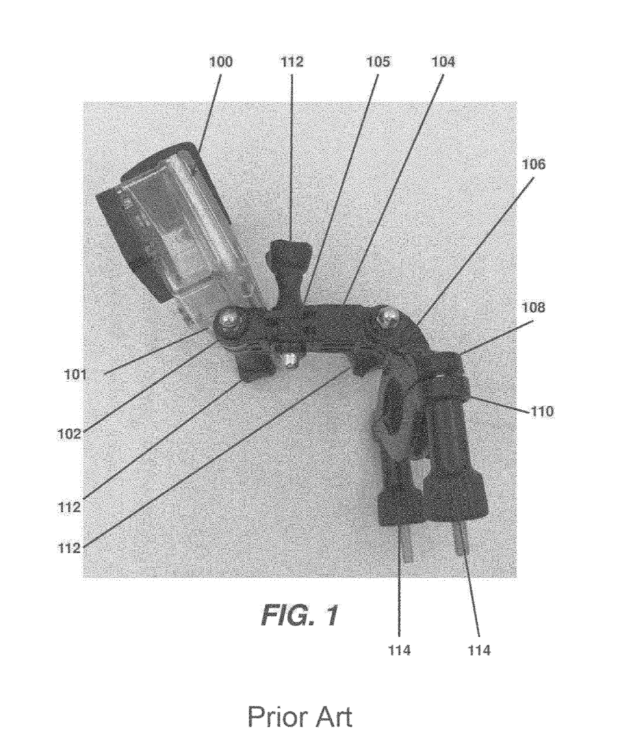
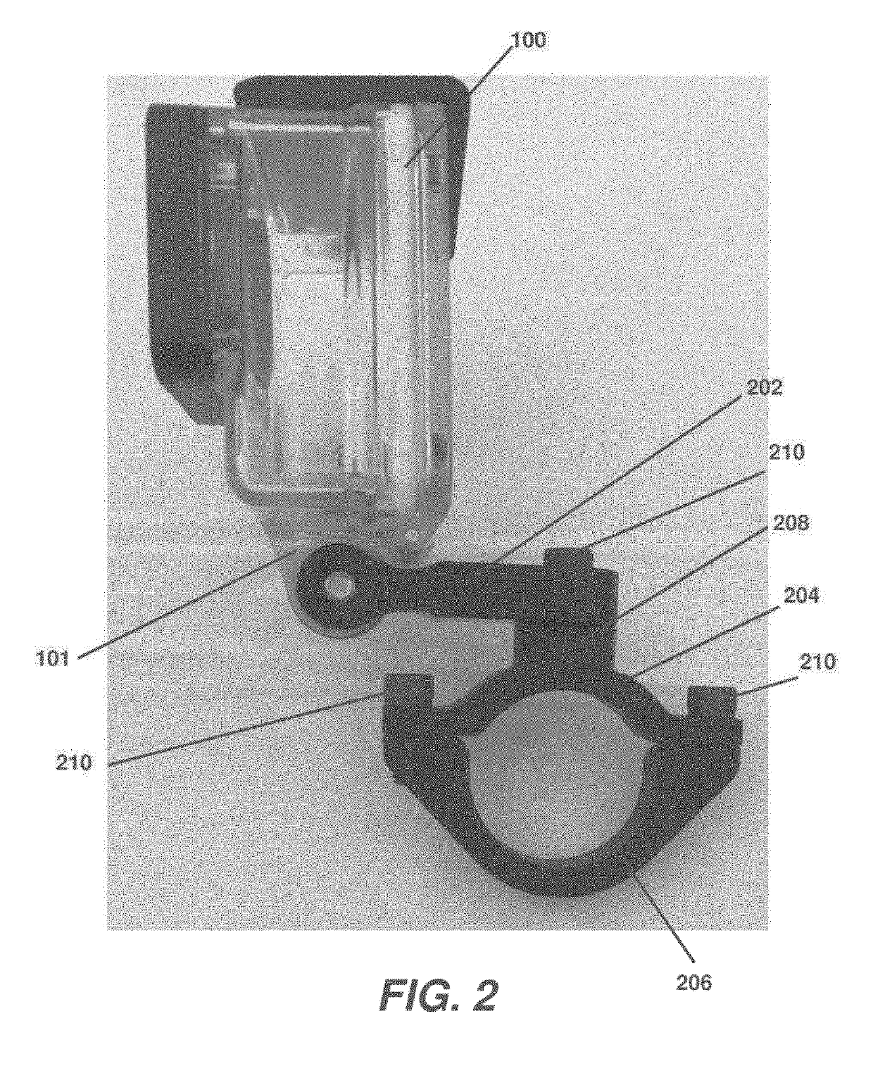
[0027]As illustrated in FIG. 1, known embodiments of action camera mounting systems include a camera housing 100 that includes a mounting point 101 for attachment to a variety of brackets. As illustrated, a mounting bracket extension arm 102 may be flexibly attached to the mounting point 101. As illustrated, a second extension 104 may be provid...


PUM


Abstract

A device for mounting an action camera to a protrusion includes a fastener and a mounting arm configured to be secured to the action camera. The mounting arm has a first opening configured to accommodate a fastener. An upper bracket has a second opening positioned to be aligned with the first opening and configured to accommodate the fastener. A lower bracket is configured to be selectively secured to the upper bracket. The upper bracket and the lower bracket are configured to surround and frictionally engage the protrusion.

Description

CROSS-REFERENCE TO RELATED APPLICATION[0001]This application claims the benefit of U.S. Provisional Application Serial No. 62 / 579,596 filed Oct. 31, 2017, the disclosures of which are hereby incorporated by reference in their entireties.TECHNICAL FIELD[0002]Exemplary embodiments of the present invention relate generally to a system for affixing rugged cameras (referred to herein as “action cameras”) to various structures.BACKGROUND AND SUMMARY OF THE INVENTION[0003]Action cameras such as the GoPro® Hero® (www.gopro.com) are ruggedized, high performance point and shoot style cameras that sometimes are configured to capture images upon demand, at set intervals, or to capture continuous or periodic video recordings. These action cameras have become very common and are used by many to record activities where non-ruggedized cameras would likely be damaged by water, impact, vibration or other conditions for which they are not adequately designed. Action cameras are frequently designed to ...

Claims


Application Information

Patent Timeline
Patent Type & Authority Applications(United States)
IPC IPC(8): G03B17/56F16M13/02F16M11/06
CPCG03B17/561F16M13/022F16M11/06F16M13/02F16M11/10F16M11/2014F16B23/0092B62J11/00
Inventor FOLKERTS, TIM
Owner IWON
Why Eureka
Try Eureka