Jewelry spring ring clasp assembly

a technology of spring ring and clasp, which is applied in the field of jewelry items, can solve the problems of difficult placement and often unattractive afterthought of the conventional art of jewelry clasps

Active Publication Date: 2019-05-09
DE LOS SANTOS CLARISSE KHRISELLE RAMOS
View PDF10 Cites 9 Cited by
  • Summary
  • Abstract
  • Description
  • Claims
  • Application Information

AI Technical Summary

Benefits of technology

[0004]Examples of a jewelry spring ring clasp assembly in accordance with the present disclosure address one or more of the deficiencies of the prior art, and may include at least a ring element and a setting element. The ring element may extend circumferentially about a main axis so as to define a ring aperture through the ring element. The ring element may have a static segment and a door segment. The static segment may have an inboard face and an outboard face disposed oppositely of one another along the main axi

Problems solved by technology

The conventional art of jewelry clasps is often an una

Method used


Image

  • Jewelry spring ring clasp assembly
  • Jewelry spring ring clasp assembly
  • Jewelry spring ring clasp assembly

Examples


Embodiment Construction

[0042]Referring now to the drawings, like reference numerals designate identical or corresponding features throughout the several views.

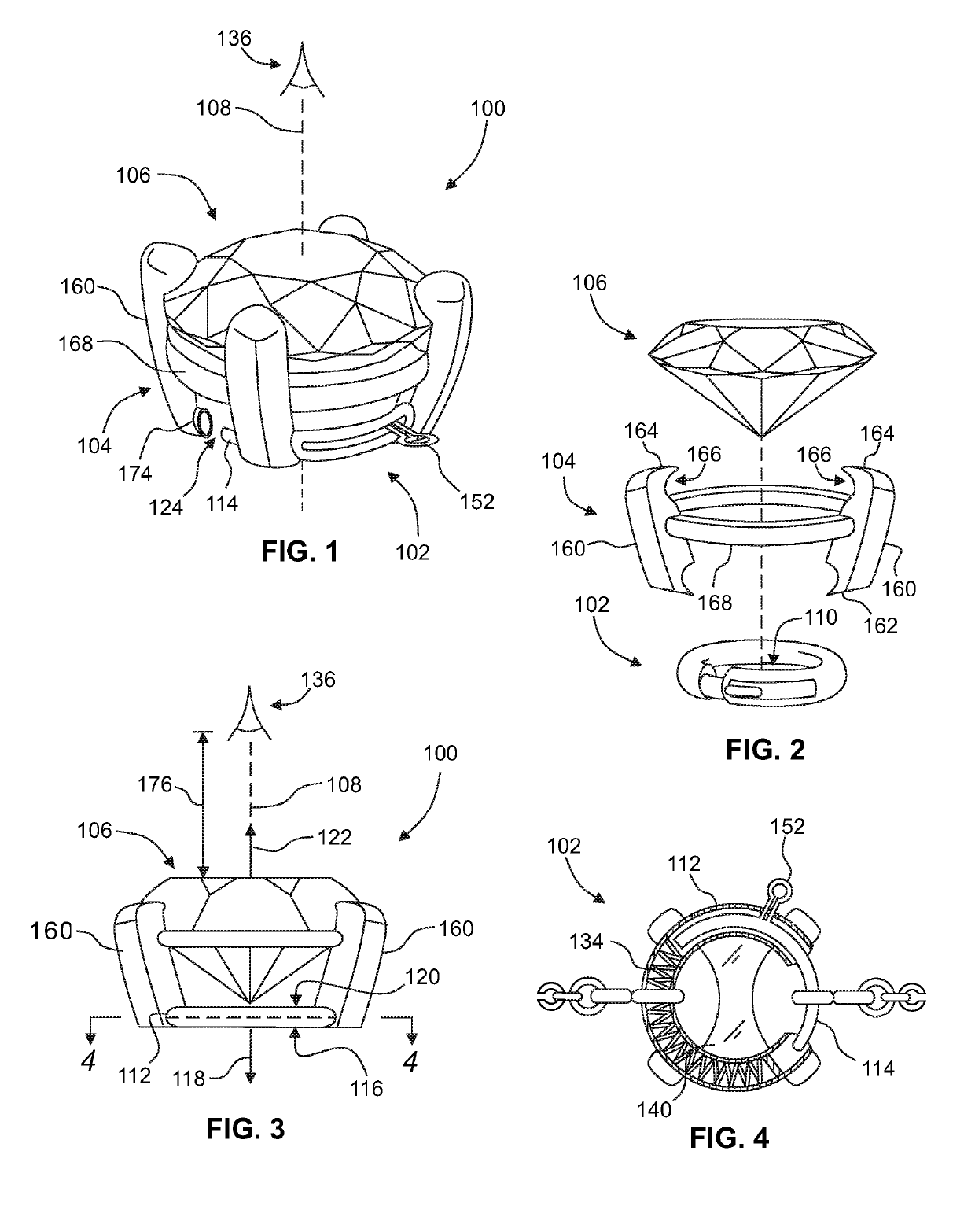
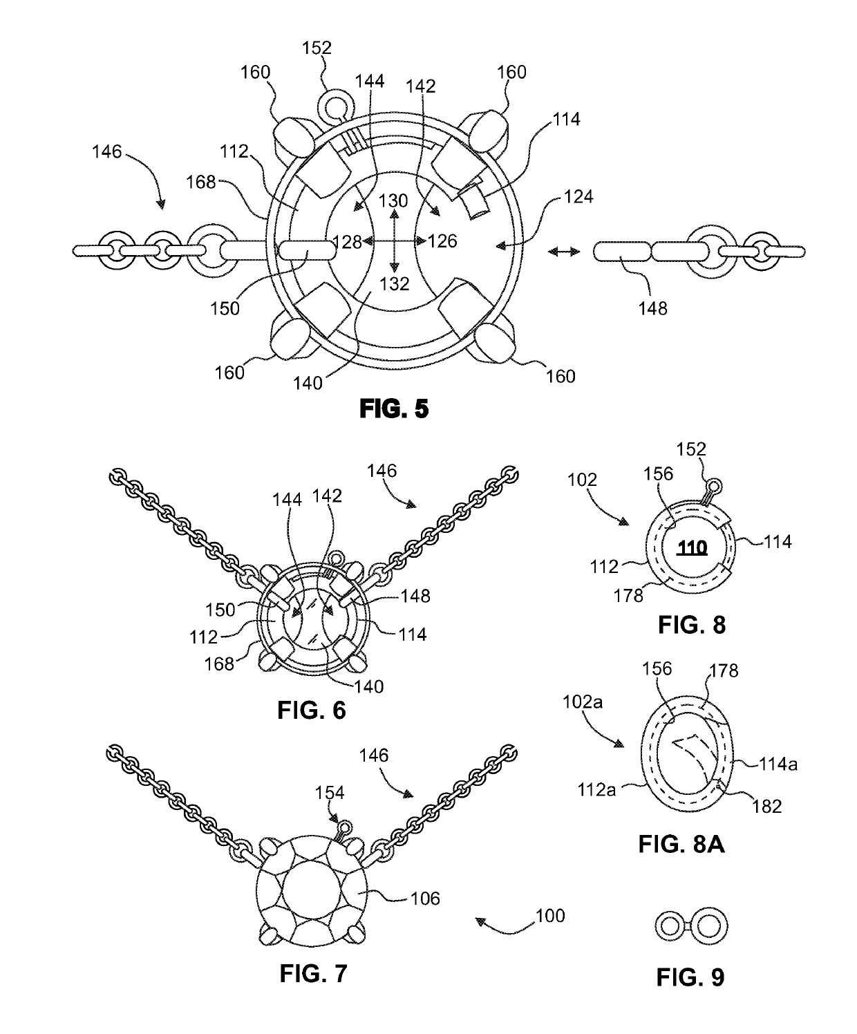
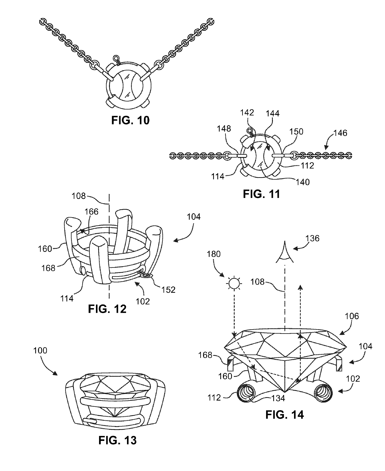
[0043]With reference to the several drawings, embodiments of a jewelry spring ring clasp assembly are shown generally at 100, and may preferably comprise at least a ring element 102 and a setting element 104. The ring element 102 may preferably extend circumferentially about a main axis 108 and thereby define a ring aperture 110 through the ring element 102. The ring element 102 may have a static segment 112 and a door segment 114. Referring to FIG. 3, the static segment 112 may have an inboard face 116 and an outboard face 120 disposed oppositely of one another along the main axis 108. An inboard direction 118 and an outboard direction 120 may be defined along the main axis 108. The static segment 112 may be arcuately discontinuous so as to define a link insertion gap 124 disposed radially of the main axis 108. The door segment 114 may be actuatabl...


PUM


Abstract

An exemplary jewelry spring ring clasp assembly includes a ring element and a setting element. The ring element extends circumferentially about a main axis to define a ring aperture therethrough. A static segment of the ring element has an inboard face and an outboard face disposed opposingly along the main axis. A door segment of the ring element is actuatable between closed and open positions. The setting element is in fixed engagement with the static segment, and is configured to retain an ornamental element in a fixed position along the main axis so that the ornamental element visually obscures the ring aperture and the ring element from a viewpoint defined outward of the outboard face. The visual obscurement may apply to at least a circumferentially-continuous portion of the ring element, and may be due in part to optical refraction through the ornamental element or optical opacity of the ornamental element.

Description

RELATED APPLICATIONS[0001]This application claims the benefit of U.S. Provisional Application No. 62 / 528,249 filed Jul. 3, 2017, the content of which is incorporated by this reference its entirety for all purposes as if fully set forth herein.TECHNICAL FIELD[0002]The disclosure herein relates generally to items of jewelry such as necklaces. More particularly, disclosed herein are devices and methods for improving the visual aesthetics of a jewelry spring ring clasp mechanism.BACKGROUND[0003]The conventional art of jewelry clasps is often an unattractive afterthought and can be difficult to put on. Oftentimes, the fastener will move to a position not intended by the wearer. For example, a necklace pendant will frequently shift to the wearer's back and the clasp will move to the wearer's front. Furthermore, when the wearer must put on the jewelry piece themselves, conventionally the easiest way to do so is by fastening the clasp in the front then shifting it around to the back. What i...

Claims


Application Information

Patent Timeline
IPC IPC(8): A44C5/20A44C5/00A44C17/02A44C15/00
CPCA44C5/2014A44C5/00A44C17/02A44C15/005A44C5/2009
Inventor DE LOS SANTOS, CLARISSE KHRISELLE RAMOS
Owner DE LOS SANTOS CLARISSE KHRISELLE RAMOS
Why Eureka
Try Eureka