Dead-time calibration for a radiation detector

a radiation detector and calibration device technology, applied in the direction of radiation measurement, measurement devices, instruments, etc., can solve the problems of inability to eliminate by means and cannot lead to satisfactory results, and achieve the effect of reducing image artifacts

Active Publication Date: 2019-05-16
KONINKLJIJKE PHILIPS NV
View PDF0 Cites 2 Cited by
  • Summary
  • Abstract
  • Description
  • Claims
  • Application Information

AI Technical Summary

Benefits of technology

[0007]It is an object of the invention to allow for reducing image artifacts caused by dead-time inhomogeneities of a la

Problems solved by technology

These varying responses particularly result from gain variations of the detector elements, which may stem from inhomogeneities in the photon conversion yield of the detector elements, losses in charge transport, charge trapping, or variations in the performance of the readout circuitry, for example.
In these applications, radiation detectors are often operated at a high radiation flux, and it is has been observed that that th

Method used


Image

  • Dead-time calibration for a radiation detector
  • Dead-time calibration for a radiation detector

Examples


Embodiment Construction

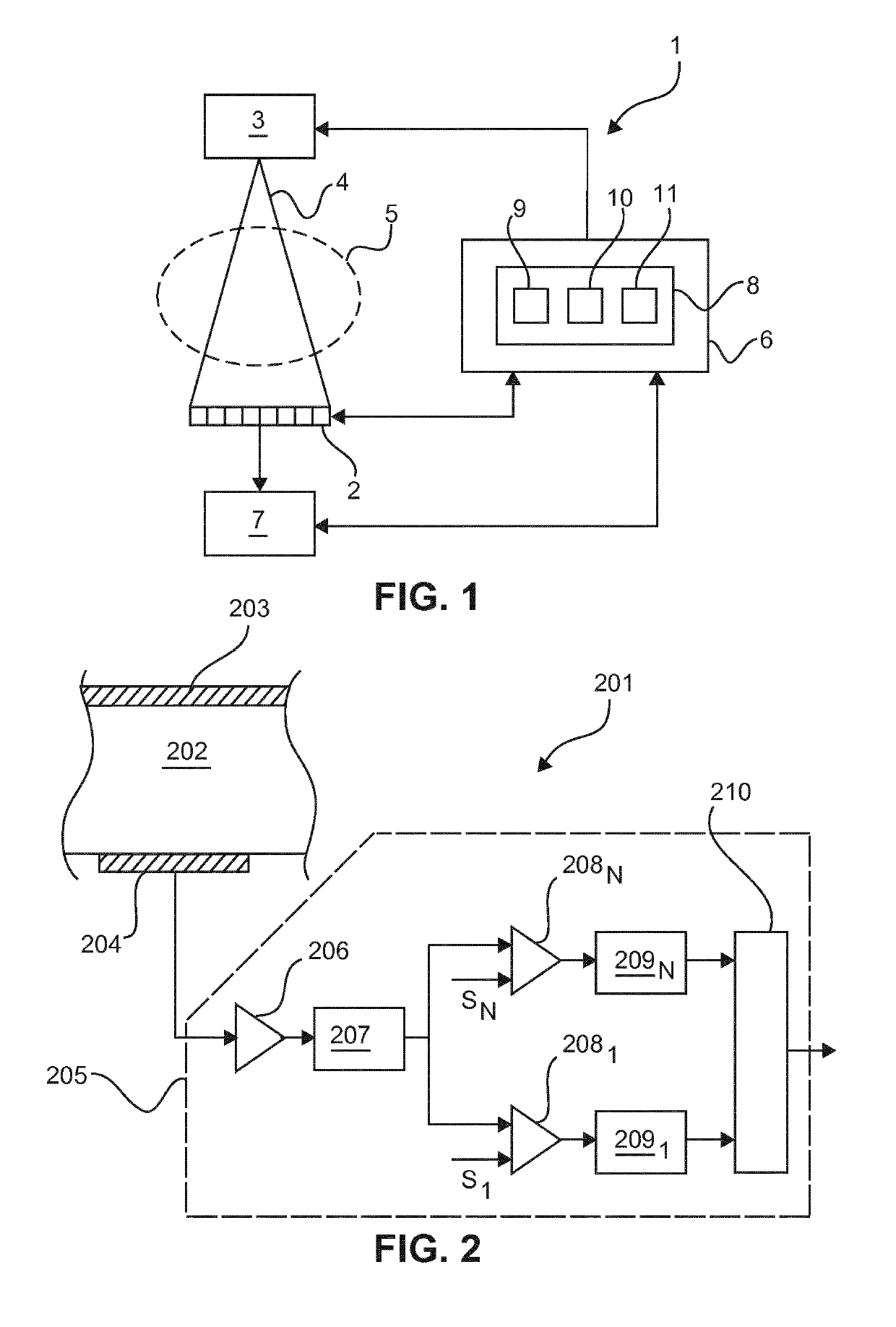
[0034]FIG. 1 schematically and exemplarily illustrates a radiation detector 2 for detecting x-ray radiation, which used in an imaging system 1. In the embodiments illustrated in the figures and described in detail herein below, the imaging system 1 is configured as a CT system for generating three-dimensional images of an object in a medical or other application, such as, for example, material testing. In other embodiments, the imaging system 1 may be configured in another way. For instance, the imaging system 1 may comprise a backscatter x-ray scanner including the radiation detector 2.

[0035]In addition to the radiation detector 2, the imaging system 1 comprises a radiation source 3, particularly an x-ray source, such as an x-ray tube. The radiation source 3 produces a radiation beam 4 which traverses an examination region 5 which is arranged between the radiation source 3 and the radiation detector 2 in case of a CT system so that the radiation detector 2 detects radiation travers...


PUM


Abstract

The invention relates to a correction device (8) for a radiation detector (2) including detector elements each for detecting incident photons. The correction device (8) is configured to read detection signals representative of an incident photon flux detected by the detector elements for different incident photon fluxes, and an evaluation unit (11) configured to determine for each detector element a dead time of the detector element and a parameter representative of an effective area of the detector element on the basis of a collective evaluation of the detection signals of the respective detector element. Further, the correction device (8) is configured to determine for each detector element correction parameters to compensate for differences in the effective areas and in the dead times of the detector elements on the basis of the determined parameters representative of the effective area and the determined dead times of the detector elements.

Description

FIELD OF THE INVENTION[0001]The invention generally relates to a correction of inhomogeneities of detector elements of photon-counting radiation detectors. More specifically, the invention relates to a correction device for a radiation detector including detector elements each for detecting photons incident onto the detector element and configured to provide a detection signal in accordance with the detected photons and to a correction method for such a radiation detector.BACKGROUND OF THE INVENTION[0002]In imaging applications, radiation detectors for detecting x-ray radiation usually consist of a plurality of detector elements often also referred to as pixels. Since the individual detector elements and the associated read-out circuitry are usually not entirely identical, the responses of the detector elements to incident radiation often vary between different detector elements. These varying responses particularly result from gain variations of the detector elements, which may ste...

Claims


Application Information

Patent Timeline
IPC IPC(8): G01T1/17G01T1/24G01T7/00
CPCG01T1/171G01T1/247G01T7/005
Inventor ROESSL, EWALDSTEADMAN BOOKER, ROGER
Owner KONINKLJIJKE PHILIPS NV
Why Eureka
Try Eureka