Backside silicon wafer design reducing image artifacts from infrared radiation

a technology of infrared radiation and backside silicon, which is applied in the direction of electrical equipment, semiconductor devices, radiation control devices, etc., can solve the problems of large image artifacts, artifacts created in image sensors, and pixels can create large image artifacts, so as to reduce ir contact with dark pixels and reduce image artifacts

Active Publication Date: 2009-08-18
APTINA IMAGING CORP
View PDF44 Cites 22 Cited by
  • Summary
  • Abstract
  • Description
  • Claims
  • Application Information

AI Technical Summary

Benefits of technology

[0014]The present invention provides imaging devices having reduced image artifacts by significantly reducing or redirecting IR radiation penetrating into the imager substrate and therefore reducing IR contact with dark pixels. In particular, the invention is applicable for any micro-electronic or micro-optical device that requires high quality micro-lenses such as, for example, CCD imagers and CMOS imagers.
[0015]The present invention provides a method for reducing image artifacts in a solid state imager having a pixel cell array, wherein the image artifacts are reduced by significantly reducing or redirecting IR radiation penetrating into the imager substrate. The present invention also reduces image artifacts in a solid state imager by significantly reducing or redirecting IR radiation from penetrating into the backside of the substrate. In one embodiment of the invention, the IR radiation is significantly reduced or redirected by applying an antireflective coating and / or an absorption layer to the backside of the imager substrate.
[0016]In another embodiment of the invention, the IR radiation is significantly reduced or redirected by modifying the backside surface of the imager substrate.
[0017]In another embodiment of the invention, the IR radiation is significantly reduced or redirected by modifying the spacing of the active pixels and the dark pixels in the imager. Also provided are methods for forming the imaging devices of the present invention having reduced image artifacts.

Problems solved by technology

One problem with image devices are the creation of artifacts.
Penetration of infrared (IR) radiation to the substrate may create artifacts in the image sensors.
Because of the small number of dark pixels used to calculate the reference signal, usually the dark reference signal is calculated from averaging of 32 or 64 dark pixels, a small change in signals from dark pixels can create large image artifacts.
Reflected IR radiation or IR radiation penetrating through the backside of the wafer can create general image artifacts as well.
The problem of reflected IR radiation in the 800 nm to 1150 nm range is increased for thinner background wafers due to the smaller total optical path of IR radiation hitting dark pixels.

Method used


Image

  • Backside silicon wafer design reducing image artifacts from infrared radiation
  • Backside silicon wafer design reducing image artifacts from infrared radiation
  • Backside silicon wafer design reducing image artifacts from infrared radiation

Examples


first embodiment

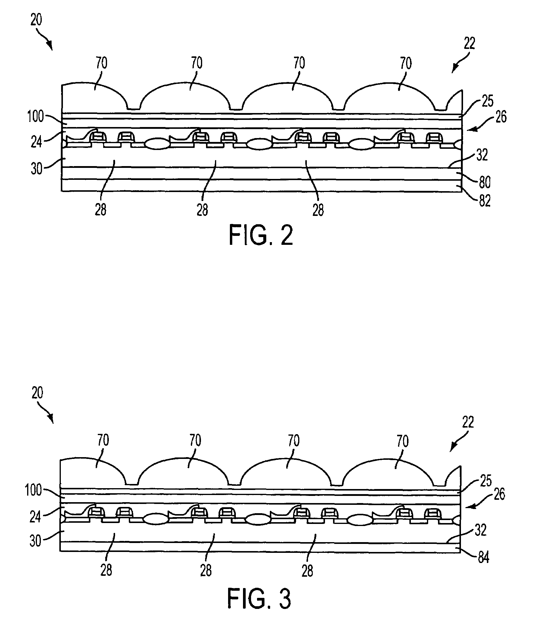
[0043]Referring now to the drawings, where like elements are designated by like reference numerals. Reference is now made to FIG. 2, which schematically shows a solid-state imager 20 according to the present invention. The imager 20 comprises a color filter layer 100 and a spacer layer 25 formed over a pixel cell array 26 as part of the same substrate 30, which may be any of the types of substrate described above. A micro-lens array 70 is formed over the color filter layer 100 and spacer layer 25. The pixel cell array 26 comprises a plurality of pixel sensor cells 28 formed in and over a first surface of the substrate 30, and is covered by a protective layer 24 which includes a passivation and planarization layer for the imager 20 as well as various metalization layers for connections. The passivation layer included in protective layer 24 may be a layer of BPSG, PSG, BSG, silicon dioxide, silicon nitride, polyimide, or other well-known light transmissive insulator. The metallization...

second embodiment

[0048]Reference is now made to FIG. 3 which schematically illustrates the solid-state imager 20 of the present invention. The illustrated FIG. 3 embodiment comprises a micro-lens array 70 formed over a color filter layer 100 and spacer layer 25, which are formed over a pixel cell array 26 formed in and / or over a first surface of substrate 30, which may be any of the types of substrate described above. The imager 20 further comprises an absorption layer 84 formed on a second surface 32 of the substrate 30. The absorption layer 84 may be formed of any suitable material which absorbs IR radiation at the wavelength of between about 800 to about 1150 nm. Preferably the absorption layer 84 is formed from Ge, SiGe, SiC, or the like. Most preferably, the absorption layer 84 is formed from germanium, as germanium for these purposes can be deposited on the surface of the substrate 30 using standard vacuum deposition techniques. While the absorption layer 84 is illustrated as a single layer, i...

third embodiment

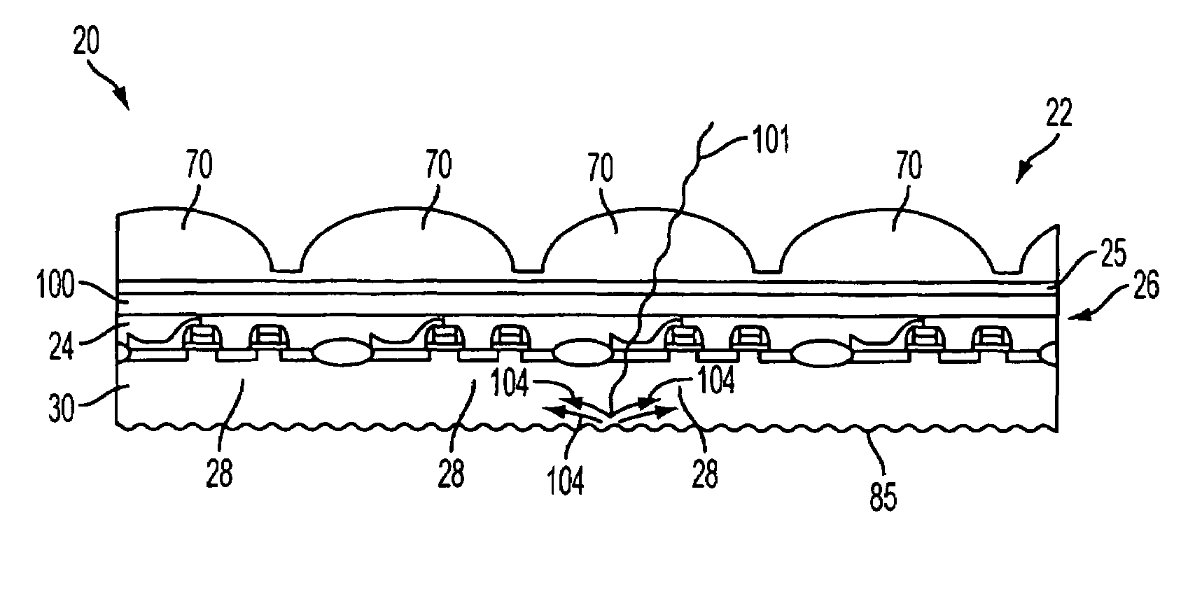
[0050]Reference is now made to FIG. 4, which schematically illustrates the solid-state imager 20 of the present invention. The illustrated embodiment comprises an imaging device having a micro-lens array 70 formed over a color filter layer 100 and spacer layer 25, which are formed over a pixel cell array 26 formed in and / or over a first surface of substrate 30. The imager 20 further comprises a roughened second substrate surface 85.

[0051]Roughening of the second substrate surface 85 in the perpendicular direction with respect to the second surface 32 provides the scattering of IR radiation instead of direct reflection to the dark pixels. Thus, the quantity of photons 101 hitting dark pixels can be reduced by scattering the photons 104 away from the dark pixels. FIG. 5 illustrates experimental results showing reducing of image artifacts from bright halogen lamp (row banding) with a roughened second surface 85 of the substrate 30. FIG. 5A is an image taken with an imaging device havin...


PUM


Abstract

Imaging devices having reduced image artifacts are disclosed. The image artifacts in the imaging devices are reduced by redirecting, absorbing or scattering IR radiation that passes through the imaging device substrate away from dark pixels.

Description

BACKGROUND OF THE INVENTION[0001]The semiconductor industry currently uses different types of semiconductor-based imagers, such as charge coupled devices (CCDs), complementary metal oxide semiconductor (CMOS) devices, photodiode arrays, charge injection devices and hybrid focal plane arrays, among others.[0002]Solid-state image sensors, also known as imagers, were developed in the late 1960s and early 1970s primarily for television image acquisition, transmission, and display. An imager absorbs incident radiation of a particular wavelength (such as optical photons, x-rays, or the like) and generates an electrical signal corresponding to the absorbed radiation. There are a number of different types of semiconductor-based imagers, including CCDs, photodiode arrays, charge injection devices (CIDs), hybrid focal plane arrays, and CMOS imagers. Current applications of solid-state imagers include cameras, scanners, machine vision systems, vehicle navigation systems, video telephones, comp...

Claims


Application Information

Patent Timeline
Patent Type & Authority Patents(United States)
IPC IPC(8): H01L29/76
CPCH01L27/1462H01L27/14625H01L27/14603H01L27/14609H01L31/0232H01L27/14685H01L27/14623H01L27/146H01L31/0236
Inventor AGRANOV, GENNADIY A.KARASEV, IGOR
Owner APTINA IMAGING CORP
Why Eureka
Try Eureka