System and method for propeller magnetic resonance imaging

a magnetic resonance imaging and propeller technology, applied in the field of mr imaging, can solve the problems of difficult combining of two sets of echoes, image artifacts may be visible, and difficult fse imaging with diffusion weighted imaging (dwi) can achieve the effect of reducing image artifacts

Active Publication Date: 2010-07-29
DIGNITY HEALTH
View PDF21 Cites 21 Cited by
  • Summary
  • Abstract
  • Description
  • Claims
  • Application Information

AI Technical Summary

Benefits of technology

[0009]It would therefore be desirable to have a system and method capable of acquiring multi-blade data in each echo spacing while reducing image artifacts.

Problems solved by technology

As a result, FSE imaging with diffusion weighted imaging (DWI) may be difficult, in general, since even minute patient motion during application of diffusion weighting gradients leaves the spins with a spatially varying and unknown starting phase prior to the spin-echo train.
This makes combining the two sets of echoes difficult.
However, image artifacts may be visible in the reconstructed images that may be caused by off-resonance magnetization, susceptibility, gradient delay, or eddy currents.

Method used


Image

  • System and method for propeller magnetic resonance imaging
  • System and method for propeller magnetic resonance imaging
  • System and method for propeller magnetic resonance imaging

Examples


Embodiment Construction

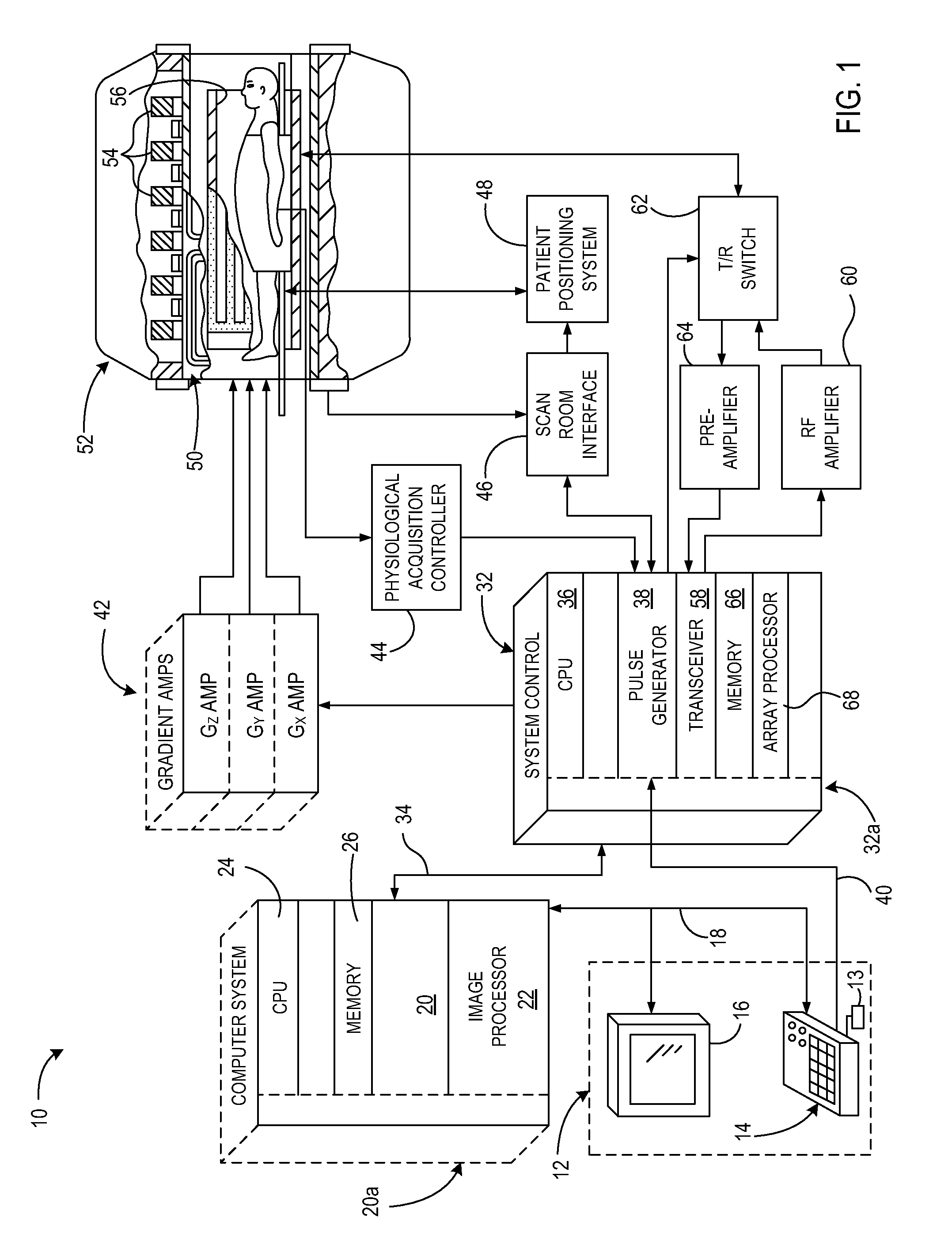
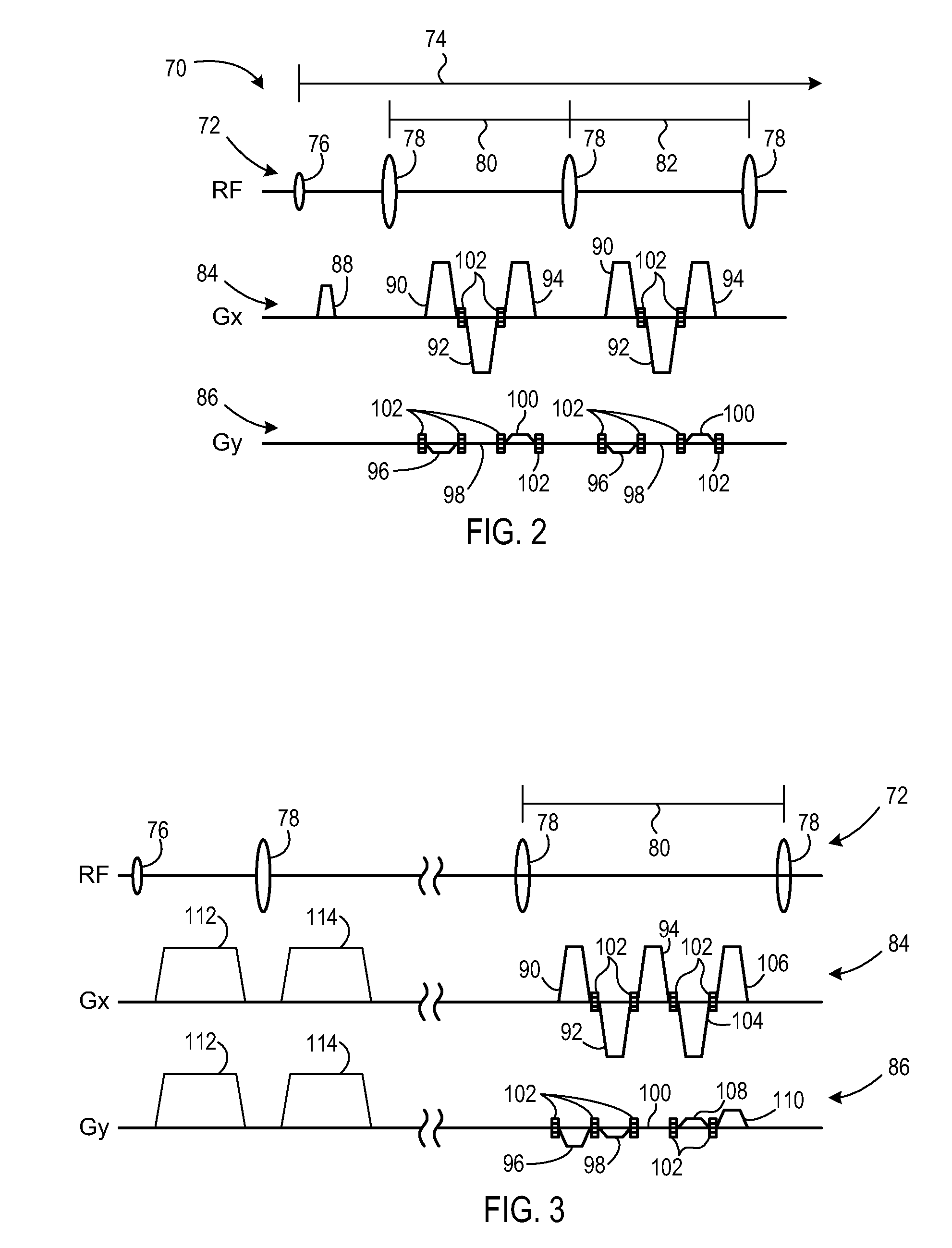
[0028]Embodiments of the present invention provide a system and method of MR imaging particularly applicable with FSE protocols that overcome the aforementioned drawbacks. Data for multiple bladelets passing through the center of k-space are acquired in each echo spacing of an echo train. The multiple bladelets are incrementally rotated about the center of k-space with each echo train until a full set of k-space data is acquired. Data for each bladelet may be acquired as a single-blade bladelet, or odd and even echoes may be acquired and used to create separate split-blade bladelet strips in k-space. Preferably, each blade extends through the center of k-space. After a phase correction, each bladelet or each corresponding odd and even bladelet pair is used for image reconstruction.

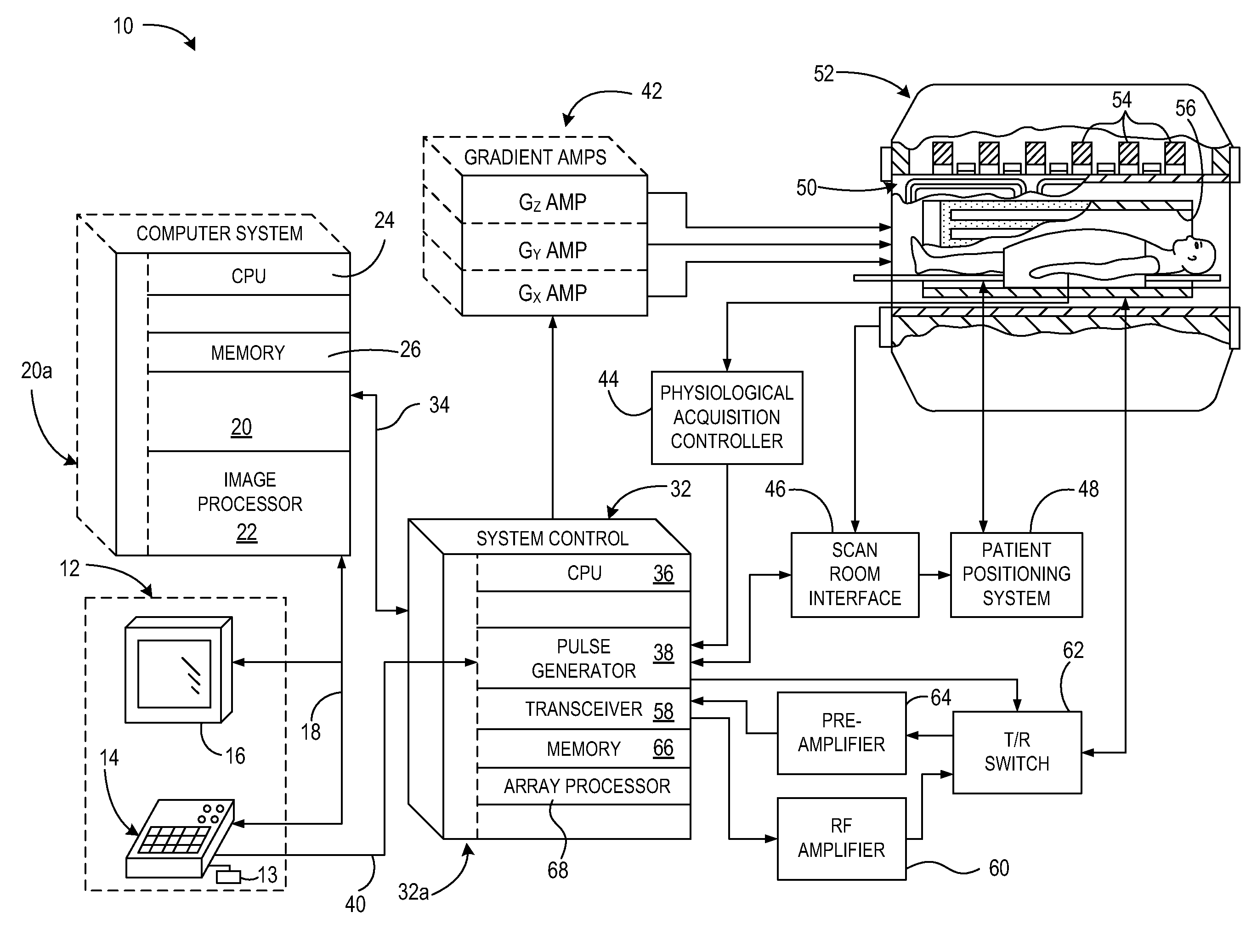
[0029]Referring to FIG. 1, the major components of a magnetic resonance imaging (MRI) system 10 incorporating the present invention are shown. The operation of the system is controlled from an operator con...


PUM


Abstract

A system and method include a computer readable storage medium having stored thereon a computer program comprising instructions which when executed by a computer cause the computer to apply a first plurality of radio frequency (RF) pulses during a first repetition time (TR) interval of a magnetic resonance (MR) pulse sequence. The instructions also cause the computer to apply a first plurality of gradient pulses and acquire the MR data during application of each gradient pulse of the first plurality of gradient pulses between an adjacent pair of RF pulses of the first plurality of RF pulses. Each gradient pulse of the first plurality of gradient pulses is configured to allow acquisition of MR data for a respective first bladelet passing through a center of k-space, wherein the first bladelets are non-parallel with each other. The instructions also cause the computer to reconstruct the acquired MR data into an image.

Description

CROSS-REFERENCE TO RELATED APPLICATIONS[0001]The present application claims the benefit of U.S. Provisional Application Serial No. 61 / 146,688 filed on Jan. 23, 2009, under 35 U.S.C. §119(e), the disclosure of which is incorporated herein by reference.BACKGROUND OF THE INVENTION[0002]The present invention relates generally to a method of MR imaging and, more particularly, to a system and method of PROPELLER magnetic resonance imaging.[0003]When a substance such as human tissue is subjected to a uniform magnetic field (polarizing field B0), the individual magnetic moments of the spins in the tissue attempt to align with this polarizing field, but precess about it in random order at their characteristic Larmor frequency. If the substance, or tissue, is subjected to a magnetic field (excitation field B1) which is in the x-y plane and which is near the Larmor frequency, the net aligned moment, or “longitudinal magnetization”, MZ, may be rotated, or “tipped”, into the x-y plane to produce...

Claims


Application Information

Patent Timeline
Patent Type & Authority Applications(United States)
IPC IPC(8): G01R33/48
CPCG01R33/4824G01R33/56341G01R33/5617G01R33/5611
Inventor HUO, DONGLAIPIPE, JAMES GRANT
Owner DIGNITY HEALTH
Why Eureka
Try Eureka