System and method for integration of a calibration target into a C-arm

a calibration target and c-arm technology, applied in the field of imaging and imageguided navigation, can solve the problems of low repeatability, high distortion of intraoperative x-ray images taken by c-arm fluoroscopes alone, and difficulty in accurately determining the position of instruments in objects or environments by visual inspection, so as to improve coordinate frame registration and tracking accuracy.

Active Publication Date: 2008-03-18
STRYKER EURO OPERATIONS HLDG LLC
View PDF7 Cites 22 Cited by
  • Summary
  • Abstract
  • Description
  • Claims
  • Application Information

AI Technical Summary

Benefits of technology

[0042]In an embodiment, the calibration fixture includes a plurality of peaks and valleys to create a low frequency signal for characterizing the image acquisition device. The calibration fixture may be positioned between the image acquisition device and an energy source such that a distance between the image acquisition device and the calibration fixture is minimized. For example, size of an imaging system may be reduced while helping to maximize available patient space.
[0045]In an embodiment, the method also includes characterizing the image acquisition device to improve registration between points in an image reference frame and points in a navigation reference frame. Image data obtained using the image acquisition device may be processed to reduce image artifacts. In an embodiment, the method includes analyzing image data of the calibration fixture in a frequency domain. The data may be translated from the frequency domain to a spatial domain after analysis. The data may be analyzed using a Fourier analysis and / or other analysis method(s).

Problems solved by technology

That is, a tracking system may be used in other settings where the position of an instrument in an object or an environment is difficult to accurately determine by visual inspection.
By contrast, fluoroscopic views may be distorted.
Intraoperative x-ray images taken by C-arm fluoroscopes alone have both a high degree of distortion and a low degree of repeatability, due largely to deformations of the basic source and camera assembly, and to intrinsic variability of positioning and image distortion properties of the camera.
In an intraoperative sterile field, such devices are typically draped, which may impair optical or acoustic signal paths of the signal elements they employ to track the patient, tool or camera.
The procedure of correlating the lesser quality and non-planar fluoroscopic images with planes in the 3-D image data sets may be time-consuming.
In techniques that use fiducials or added markers, a surgeon may follow a lengthy initialization protocol or a slow and computationally intensive procedure to identify and correlate markers between various sets of images.
Correlation of patient anatomy or intraoperative fluoroscopic images with precompiled 3-D diagnostic image data sets may also be complicated by intervening movement of the imaged structures, particularly soft tissue structures, between the times of original imaging and the intraoperative procedure.
In cases where a growing tumor or evolving condition actually changes the tissue dimension or position between imaging sessions, further confounding factors may appear.
While various jigs and proprietary subassemblies have been devised to make each individual coordinate sensing or image handling system easier to use or reasonably reliable, the field remains unnecessarily complex.
Not only do systems often use correlation of diverse sets of images and extensive point-by-point initialization of the operating, tracking and image space coordinates or features, but systems are subject to constraints due to the proprietary restrictions of diverse hardware manufacturers, the physical limitations imposed by tracking systems and the complex programming task of interfacing with many different image sources in addition to determining their scale, orientation, and relationship to other images and coordinates of the system.
This is a complex undertaking, since the nature of the fluoroscope's 3D to 2D projective imaging results in loss of a great deal of information in each shot, so the reverse transformation is highly underdetermined.
Changes in imaging parameters due to camera and source position and orientation that occur with each shot further complicate the problem.
However, this appears to be computationally very expensive, and the current state of the art suggests that while it may be possible to produce corrected fluoroscopic image data sets with somewhat less costly equipment than that used for conventional CT imaging, intra-operative fluoroscopic image guidance will continue to involve access to MRI, PET or CT data sets, and to rely on extensive surgical input and set-up for tracking systems that allow position or image correlations to be performed.
Additionally, gravity may affect geometry of an x-ray system.
A difference between an imaging angle and an angle of the Earth's magnetic field may cause distortion that affects a resulting image.
Additionally, an operator or patient may bump the C-arm or other component of an imaging system during operation or positioning, which may affect a resulting image.
However, registration using a reference unit located on the patient and away from the fluoroscope camera introduces inaccuracies into coordinate registration due to distance between the reference unit and the fluoroscope.
Additionally, the reference unit located on the patient is typically small or else the unit may interfere with image scanning.
A smaller reference unit may produce less accurate positional measurements, and thus impact registration.
However, use of BBs or other calibration markers in a fixture may impose distortion or artifacts in resulting images.
Both of the methods described suffer from disadvantages.
Wear and damage to the device may affect the accuracy of the stored parameters.
Furthermore, there may be situations where the user unknowingly is flexing the C-arm by unintended collision with the operating table.
The second method suffers from image degradation from the removal of the image artifacts.
Also, the depth of the calibration phantom (e.g., 8-10 cm) compromises the usable patient volume between the x-ray source and detector.

Method used


Image

  • System and method for integration of a calibration target into a C-arm
  • System and method for integration of a calibration target into a C-arm
  • System and method for integration of a calibration target into a C-arm

Examples


Embodiment Construction

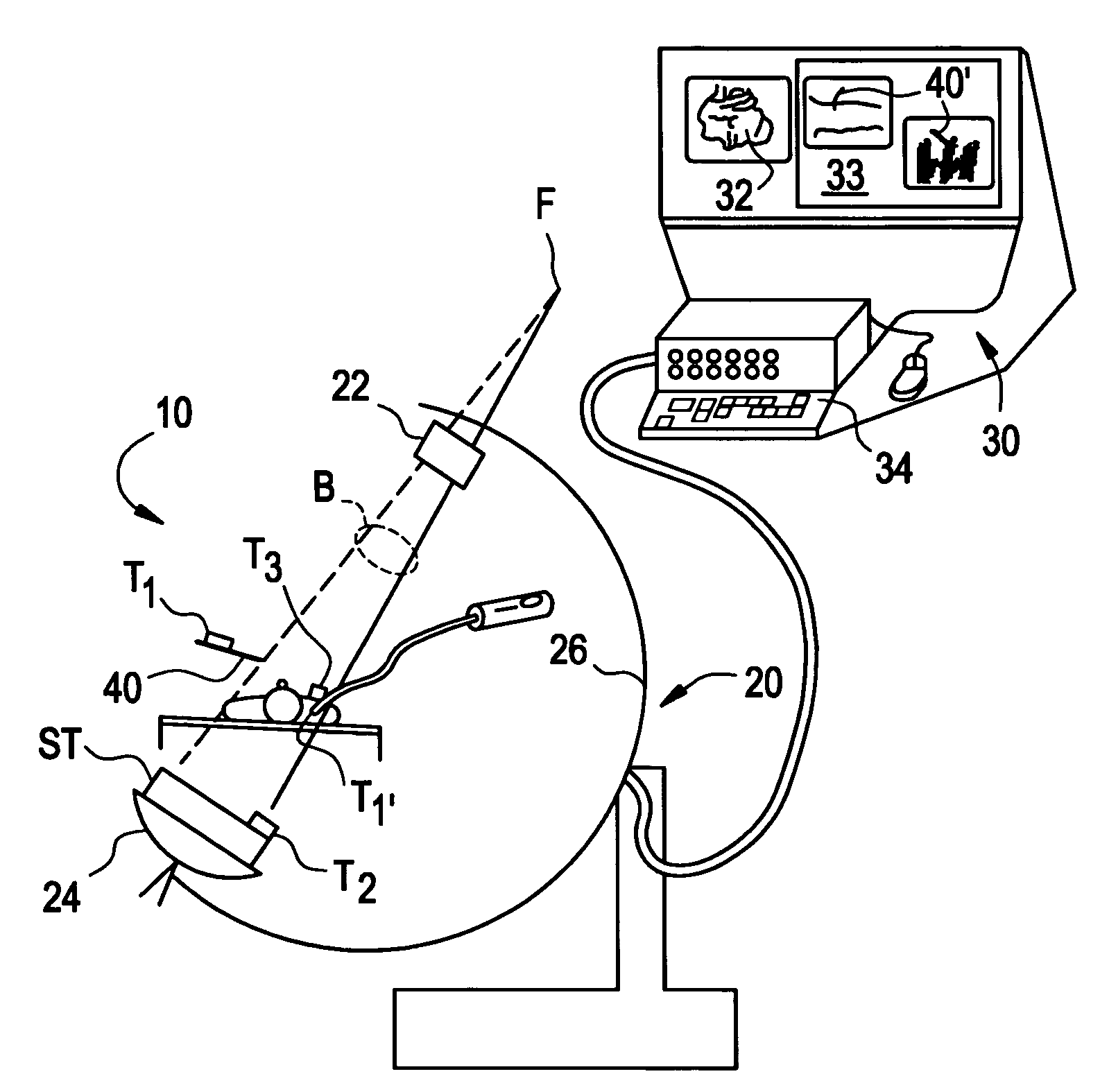
[0061]FIG. 3 illustrates an imaging system 10 in accordance with an embodiment of the present invention for use in an operating room environment. As shown in FIG. 3, the system 10 includes a fluoroscope 20, a work station 30 having one or more displays 32 and a keyboard / mouse or other user interface 34, and a plurality of tracking elements T1, T2, T3. The fluoroscope 20 is illustrated as a C-arm fluoroscope in which an x-ray source 22 is mounted on a structural member or C-arm 26 opposite to an x-ray receiving and detecting unit, referred to herein as an imaging assembly 24. The C-arm moves about a patient or other object to produce two dimensional projection images of the patient from different angles. The patient or object remains positioned between the source and the camera, and may, for example, be situated on a table or other support, although the patient / object may move. The tracking elements, described further below, are mounted such that one element T1 is affixed to, incorpo...


PUM


Abstract

Certain embodiments of the present invention provide a method and system for improved calibration of an image acquisition device. Certain embodiments of the system include an image acquisition device for obtaining at least one image of an object and a calibration fixture positioned in relation to the image acquisition device. The calibration fixture includes a radiotranslucent material providing low frequency content for characterizing the image acquisition device. In an embodiment, the calibration fixture includes a plurality of peaks and valleys to create a low frequency signal for characterizing the image acquisition device. The calibration fixture may be positioned between the image acquisition device and an energy source such that a distance between the image acquisition device and the calibration fixture is minimized. In certain embodiments, a grating or other calibration fixture may be used to generate a moiré pattern to calibrate the image acquisition device.

Description

RELATED APPLICATIONS[0001]The present application relates to, and claims priority from, U.S. Provisional Application No. 60 / 627,251, filed on Nov. 12, 2004, and entitled “System and Method for Integration of a Calibration Target into a C-Arm”.FEDERALLY SPONSORED RESEARCH OR DEVELOPMENT[0002][Not Applicable]MICROFICHE / COPYRIGHT REFERENCE[0003][Not Applicable]BACKGROUND OF THE INVENTION[0004]The present invention generally relates to imaging and image-guided navigation. In particular, the present invention relates to a system and method for improved calibration of equipment used in imaging and image-guided operations.[0005]Medical practitioners, such as doctors, surgeons, and other medical professionals, often rely upon technology when performing a medical procedure, such as image-guided surgery or examination. A tracking system may provide positioning information for the medical instrument with respect to the patient or a reference coordinate system, for example. A medical practition...

Claims


Application Information

Patent Timeline
Patent Type & Authority Patents(United States)
IPC IPC(8): G01D18/00
CPCA61B5/06A61B6/12A61B6/547A61B6/583A61B19/52A61B19/5244A61B19/54A61B6/4021A61B6/4291A61B2017/00725A61B2017/00902A61B2019/5238A61B2019/5251A61B6/4441A61B6/487A61B6/5205A61B6/584A61B34/20A61B90/36A61B90/39A61B2034/2051A61B2090/376
Inventor YATSENKO, DIMITRI VICTOROVICHLEA, JON THOMASLLOYD, CHARLES FREDERICK
Owner STRYKER EURO OPERATIONS HLDG LLC
Why Eureka
Try Eureka