Method for vibrating a vibration device

Active Publication Date: 2019-07-04
TDK CORPARATION
View PDF0 Cites 1 Cited by
  • Summary
  • Abstract
  • Description
  • Claims
  • Application Information

AI Technical Summary

Benefits of technology

[0003]An object of one aspect of the present invention is to provide a method for vibrat

Problems solved by technology

As the vibration device vibrates, reliability of the vibration device may decrease.
For example, a bonding state between a piezoelectric element and a vibration member may deteriorate with vibration of the vibration device.
In a case in which the bonding state between the piezoelectric element and the vibration member deteriorates, a displacement of the piezoelectric element is not properly transmitted to the vibration member, and a displacement amo

Method used


Image

  • Method for vibrating a vibration device
  • Method for vibrating a vibration device
  • Method for vibrating a vibration device

Examples


Example

[0040]Hereinafter, embodiments of the present invention will be described in detail with reference to the accompanying drawings. In the following description, the same elements or elements having the same functions are denoted with the same reference numerals and overlapped explanation is omitted.

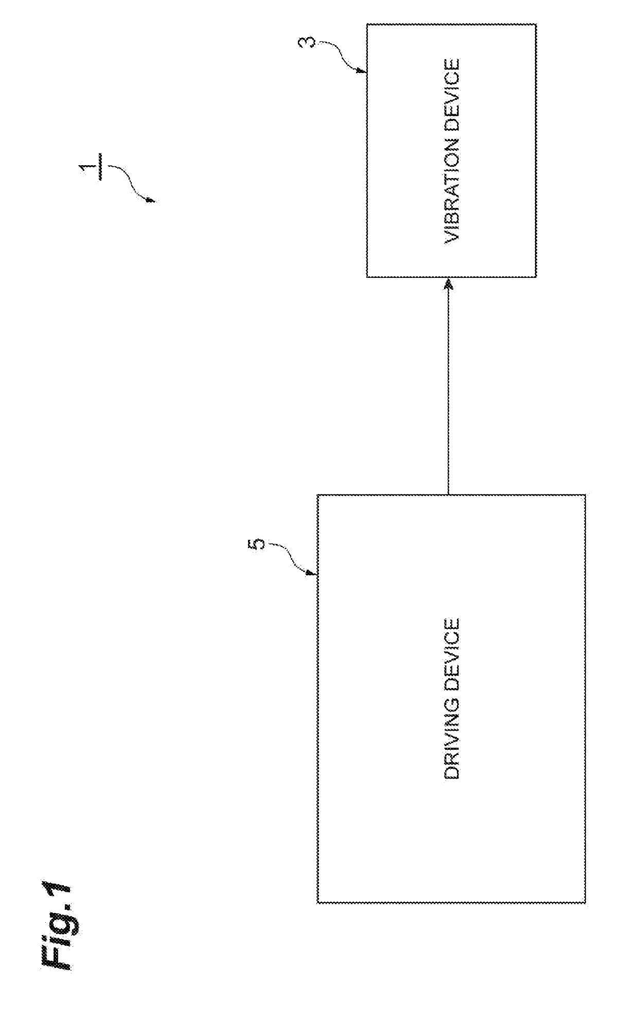
[0041]As illustrated in FIG. 1, a tactile sense presentation device 1 according to the present embodiment includes a vibration device 3 and a driving device 5.

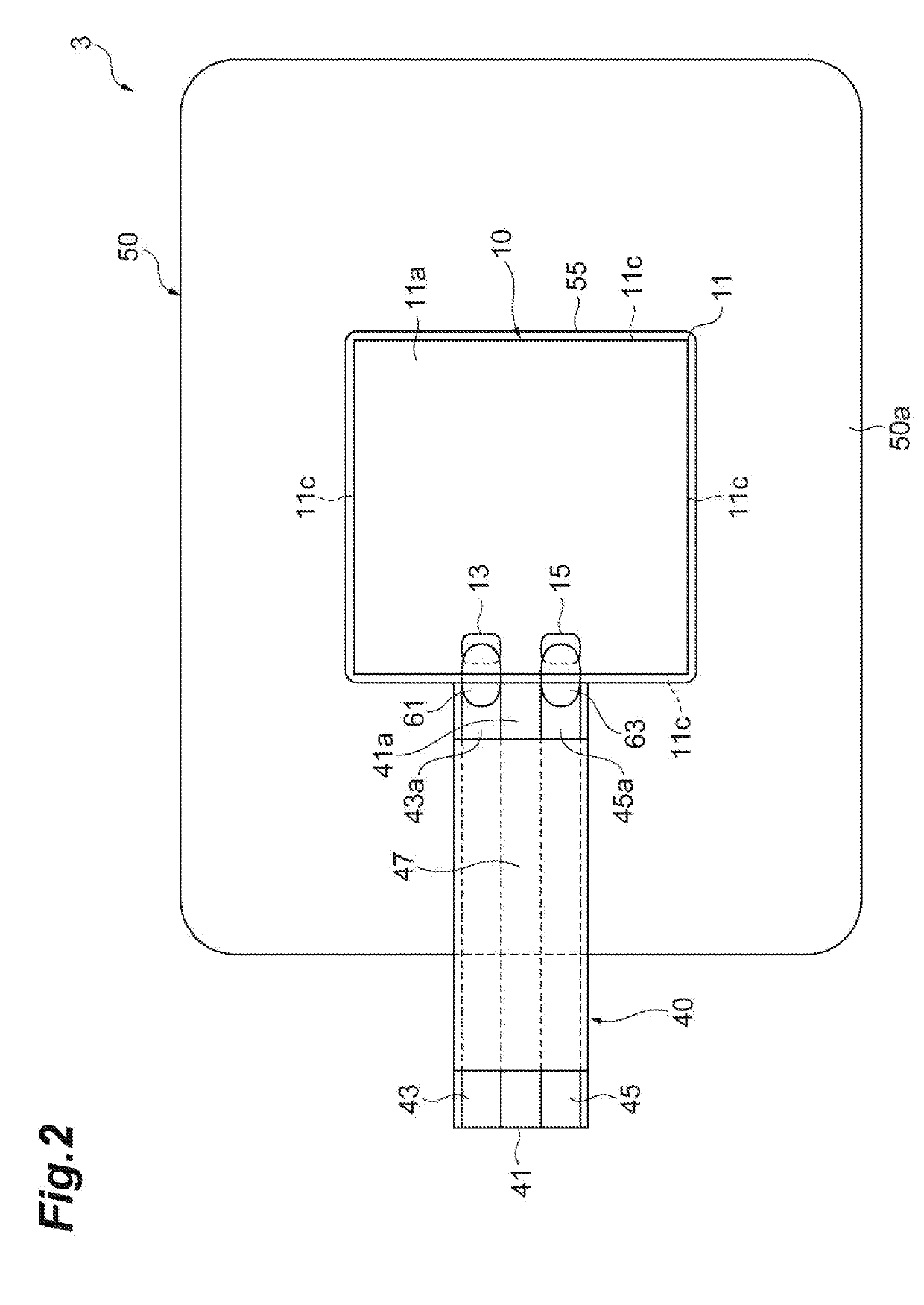
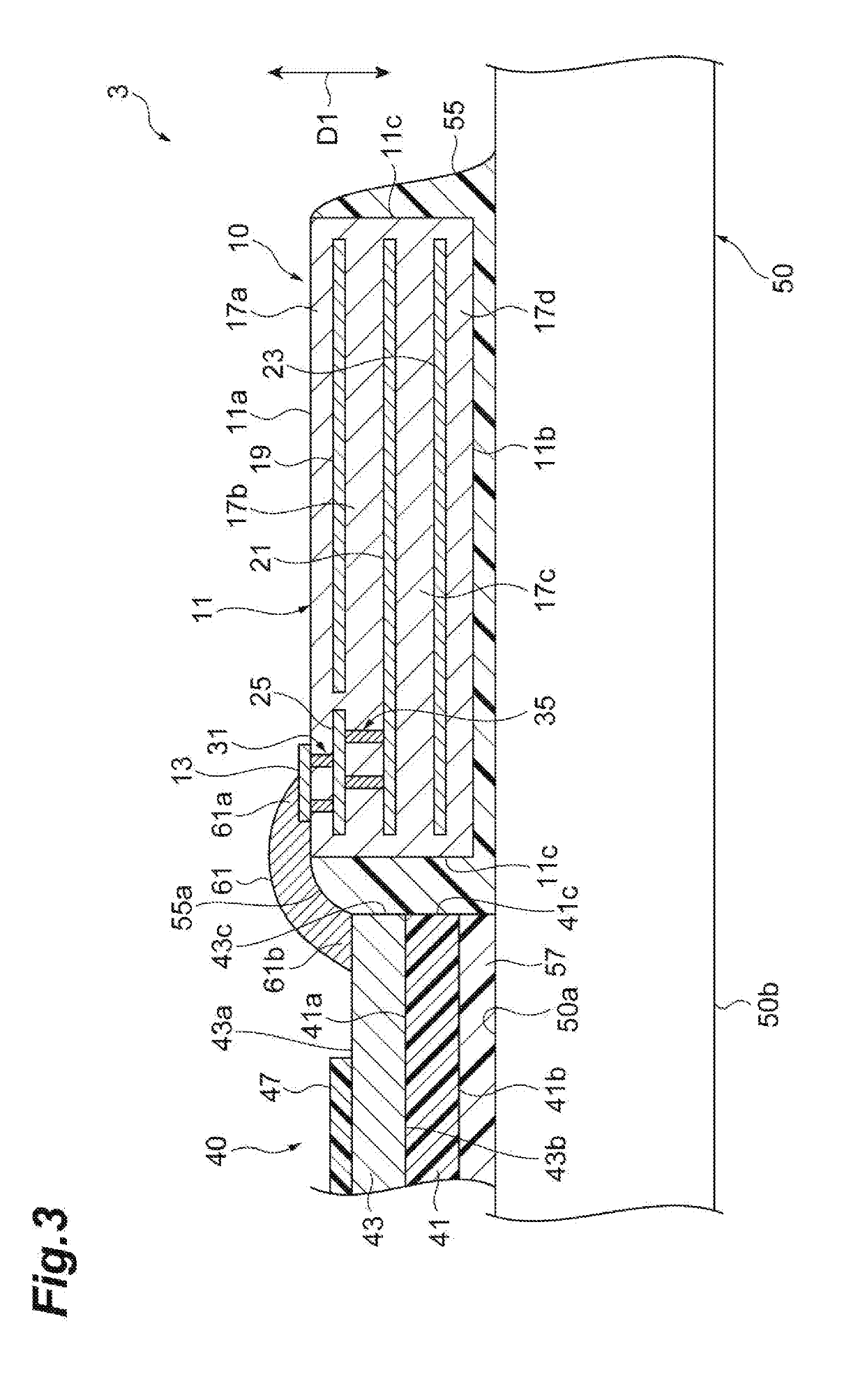
[0042]First, a configuration of the vibration device 3 will be described with reference to FIGS. 2 to 8. FIG. 2 is a plan view of the vibration device. FIGS. 3, 4, 5, and 6 are views illustrating cross-sectional configurations of the vibration device. FIG. 7 is an exploded perspective view illustrating a configuration of a piezoelectric element. FIG. 8 is a plan view of the piezoelectric element. A disclosure according to the present embodiment includes a method for vibrating the vibration device 3.

[0043]For Example, in a case in whic...


PUM


Abstract

A vibration device includes a piezoelectric element, a vibration member to which the piezoelectric element is bonded, and a wiring member connected with the piezoelectric element. A method for vibrating the vibration device includes inputting a signal including a fundamental frequency component to the piezoelectric element through the wiring member, and vibrating the vibration device in a vibration mode that includes the fundamental frequency component and does not approximately include a high order frequency component that is n times (n represents an integer of 2 or more) the fundamental frequency component. The fundamental frequency component is lower than the resonance frequency component of the vibration device.

Description

BACKGROUND OF THE INVENTION1. Field of the Invention[0001]The present invention relates to a method for vibrating a vibration device.2. Description of Related Art[0002]Known vibration devices include a piezoelectric element, a vibration member to which the piezoelectric element is bonded, and a wiring member connected with the piezoelectric element (see, for example, Japanese Unexamined Patent Publication No. 2016-051894).SUMMARY OF TB F INVENTION[0003]An object of one aspect of the present invention is to provide a method for vibrating a vibration device that suppresses a decrease in reliability of the vibration device.[0004]As a result of research and study the present inventors have discovered the following facts.[0005]As the vibration device vibrates, reliability of the vibration device may decrease. For example, a bonding state between a piezoelectric element and a vibration member may deteriorate with vibration of the vibration device. In a case in which the bonding state betw...

Claims


Application Information

Patent Timeline
IPC IPC(8): B06B1/02B06B1/06H01L41/04H01L41/047H01L41/083H01L41/09
CPCB06B1/0238B06B1/0603H01L41/042H01L41/0475H01L41/083H01L41/0973B06B1/0611G10K9/125H10N30/874H10N30/875H10N30/2047H10N30/50H10N30/802
Inventor KIJIMA, KAORUSAITO, KAZUKI
Owner TDK CORPARATION
Why Eureka
Try Eureka