Liquid ejection head circuit board and liquid ejection head

Pending Publication Date: 2022-05-19
CANON KK
View PDF0 Cites 0 Cited by
  • Summary
  • Abstract
  • Description
  • Claims
  • Application Information

AI Technical Summary

Benefits of technology

[0005]In view of the aforementioned background, an aspect of the present disclosure is to provide a liquid ejection head circuit board in which a

Problems solved by technology

The reliability of the inkjet head decreases by the dissolution of the interlayer insulating

Method used


Image

  • Liquid ejection head circuit board and liquid ejection head
  • Liquid ejection head circuit board and liquid ejection head
  • Liquid ejection head circuit board and liquid ejection head

Examples


Example

Example 1

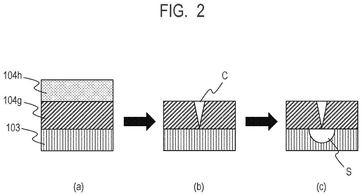
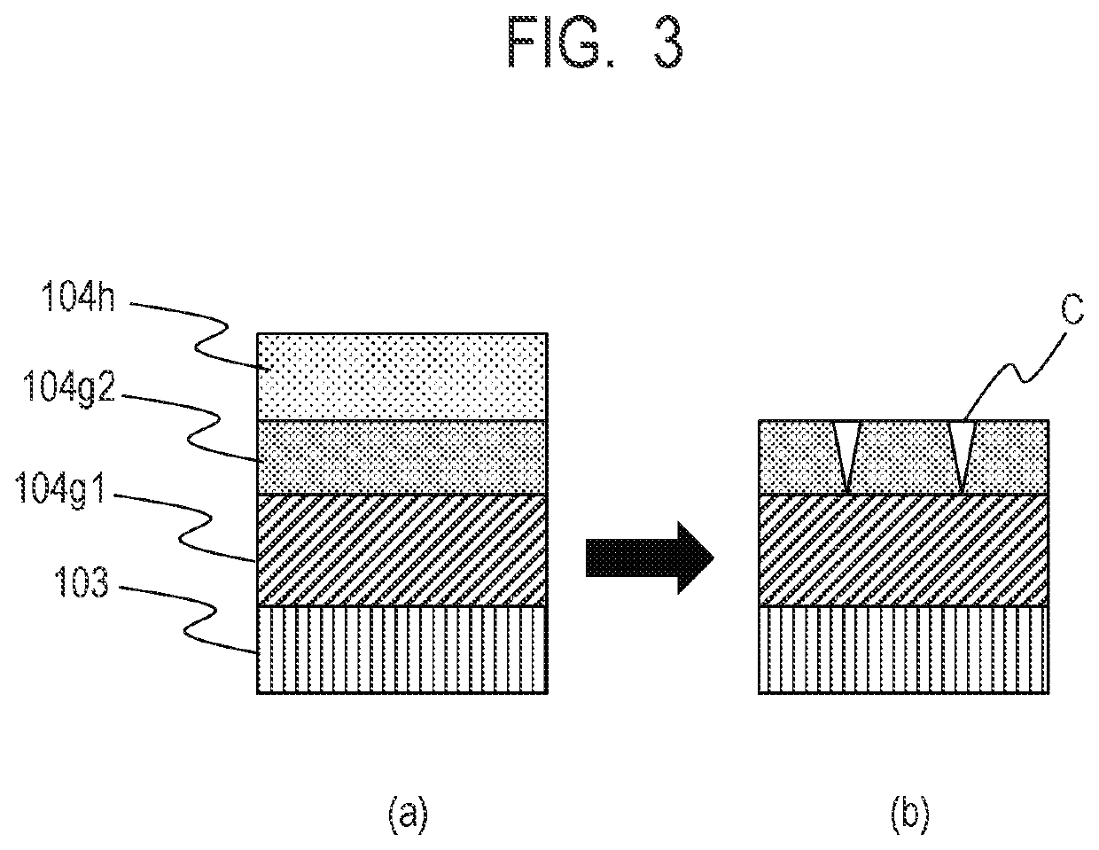
[0068]This example explains the case where resistance against a crack is improved by forming a SiOCN film with a configuration including two layers varying in C composition ratio.

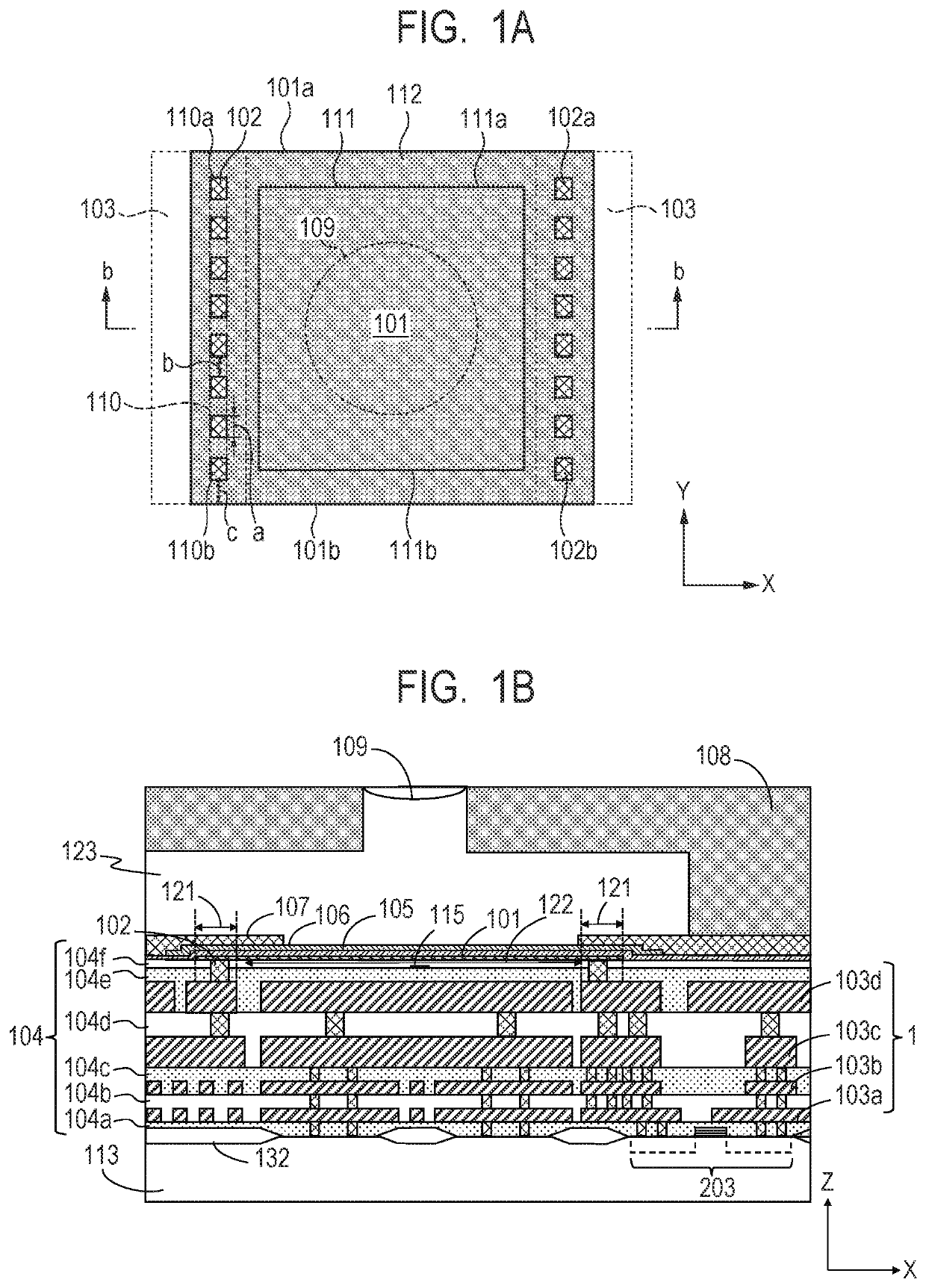
[0069]In this example, the interlayer insulating film 104e (insulating film on the ground wiring layer 103d) was a laminated film as described below.

[0070]First, a plasma SiO film was formed on the ground wiring layer 103d and was planarized and a first SiOCN film was formed on the planarized surface of the plasma SiO film. Then, a second SiOCN film was formed and another plasma SiO film was formed and planarized to obtain the laminated film.

[0071]In this case, materials with three types of compositions with greater C composition ratios than the first SiOCN film (differences in C composition ratio to the first SiOCN film were 2 at. %, 5 at. %, and 7 at. %, respectively) were selected for the second SiOCN film. Moreover, the film thickness of the first SiOCN film was fixed to 150 nm and the film thi...

Example

Example 2

[0077]This example explains the case where resistance against a crack is improved by forming a SiOCN film with a configuration including two layers varying in C composition ratio in a layer configuration different from that of Example 1.

[0078]In this example, the interlayer insulating film 104e (insulating film on the ground wiring layer 103d) was a laminated film as described below.

[0079]First, a plasma SiO film was formed on the ground wiring layer 103d and a first SiOCN film was formed on the plasma SiO film without planarization of the plasma SiO film. Then, a second SiOCN film was formed and another plasma SiO film was formed and planarized to obtain the laminated film.

[0080]In this case, materials with three types of compositions with greater C composition ratios than the first SiOCN film (differences in C composition ratio to the first SiOCN film were 2 at %. 5 at. %, and 7 at. %, respectively) were selected for the second SiOCN film. Moreover, the film thickness of ...

Example

Example 3

[0086]This example explains the case where resistance against a crack is improved by providing a low-density insulating film (low-density interlayer film) with low density on the SiOCN film.

[0087]In this example, the interlayer insulating film 104e (insulating film on the ground wiring layer 103d) was a laminated film as described below.

[0088]First, a plasma SiO film was formed on the ground wiring layer 103d and was planarized and a SiOCN film was formed on the planarized surface of the plasma SiO film. Next, a SiOC film with a lower density than the SiOCN film was formed on the SiOCN film. Then, another plasma SiO film was formed on the SiOC film and planarized to obtain the laminated film.

[0089]In this case, the SiOC film was formed in the plasma CVD method using octamethylcyclotetrasiloxane (OMCTS) and oxygen (O2) as raw materials. Three types of SiOC films varying in density were individually formed by adjusting film formation conditions. The density difference between...


PUM


Abstract

A liquid ejection head circuit board including a substrate, a heat generating resistance element that generates heat energy used for ejection of liquid, an electric wiring layer that is electrically connected to the heat generating resistance element, and an insulating film that insulates the electric wiring layer. The insulating film includes a first insulating film and a second insulating film on the first insulating film, the first insulating film is a first SiOCN film, and the second insulating film is a second SiOCN film containing more carbon than the first SiOCN film or a low-density insulating film with a lower density than the first SiOCN film.

Description

BACKGROUND OF THE INVENTIONField of the Invention[0001]The present disclosure relates to a liquid ejection head circuit board and a liquid ejection head.Description of the Related Art[0002]As one of recording methods using an inkjet head that is a typical liquid ejection head, there is a method in which a heat generating element heats ink to cause bubbling and the ink is ejected by using these air bubbles.[0003]Japanese Patent Application Laid-Open No. 2016-137705 describes a technique in which, in an inkjet head, an insulating body such as SiO is used as an interlayer insulating film that electrically insulates multiple electrical wiring layers from one another and the electrical wiring layer and a heat generating element from each other.[0004]When the inkjet head that employs SiO as the interlayer insulating film and that is disclosed in Japanese Patent Application Laid-Open No. 2016-137705 is used for a long period with the ink entering the interior of the liquid ejection head ci...

Claims


Application Information

Patent Timeline
IPC IPC(8): B41J2/14
CPCB41J2/14072B41J2002/14185B41J2/14032B41J2/14112B41J2/14129B41J2/1603B41J2/1642B41J2202/13B41J2202/03
Inventor TAKAHASHI, KENJIHIROHARA, MAIMINAMI, SEIKO
Owner CANON KK
Why Eureka
Try Eureka