Eureka AIR delivers breakthrough ideas for toughest innovation challenges, trusted by R&D personnel around the world.

Safety Helmet

Active Publication Date: 2019-08-01
KLEIN TOOLS INC
View PDF0 Cites 12 Cited by
  • Summary
  • Abstract
  • Description
  • Claims
  • Application Information

AI Technical Summary

Benefits of technology

The present invention is about safety helmets that can be customized with removable modules such as headlamps, cameras, speakers, and cellphones. These helmets have two mounts on either the front or back sides, making them easy to attach. The helmets also have an integrated battery and electrical leads, allowing for the addition of lighter removable devices without sacrificing battery power. The removable devices can be easily removed and replaced for charging. The technical effects of this invention are that it provides a flexible and customizable safety helmet that allows for added safety features and provides more flexibility and comfort for users.

Problems solved by technology

While use of elastic bands can permit mounting of the headlamp at any orientation relative to the safety helmet, and also mounting of additional devices onto a single band, switching between orientations is difficult.
Moreover, band-type mounting systems are prone to slipping off from the safety helmet, especially when lubricating fluids may fall on the helmet and enter the interface between the helmet's exterior and the band, thus requiring constant readjustment by the user.
Another common issue with known safety helmet headlamp arrangements is the connection of a power source to the headlamp.
Portable power sources such as batteries are known to be heavy and bulky.
When integrated with the headlamp, which is worn on the front facing side of the helmet, headlamps with integrated power sources tend to pull the helmet down, especially when the wearer is looking down.
To reduce the weight of headlamps, manufacturers decrease the size of the batteries that are integrated therewith, which also decreases their useful life and will also decrease the lumen output of the headlamp.
In certain applications where long life and higher light intensity is desired such as in underground mines, headlamps are typically connected to a power source via a wire, which leads to heavier and bulkier batteries worn around the user's waist.
The wire leading to the batteries, however, can present a nuisance to the user and also increases the chances of unsafe conditions as it may become snagged as the user is moving around.

Method used


Image

  • Safety Helmet
  • Safety Helmet
  • Safety Helmet

Examples


Embodiment Construction

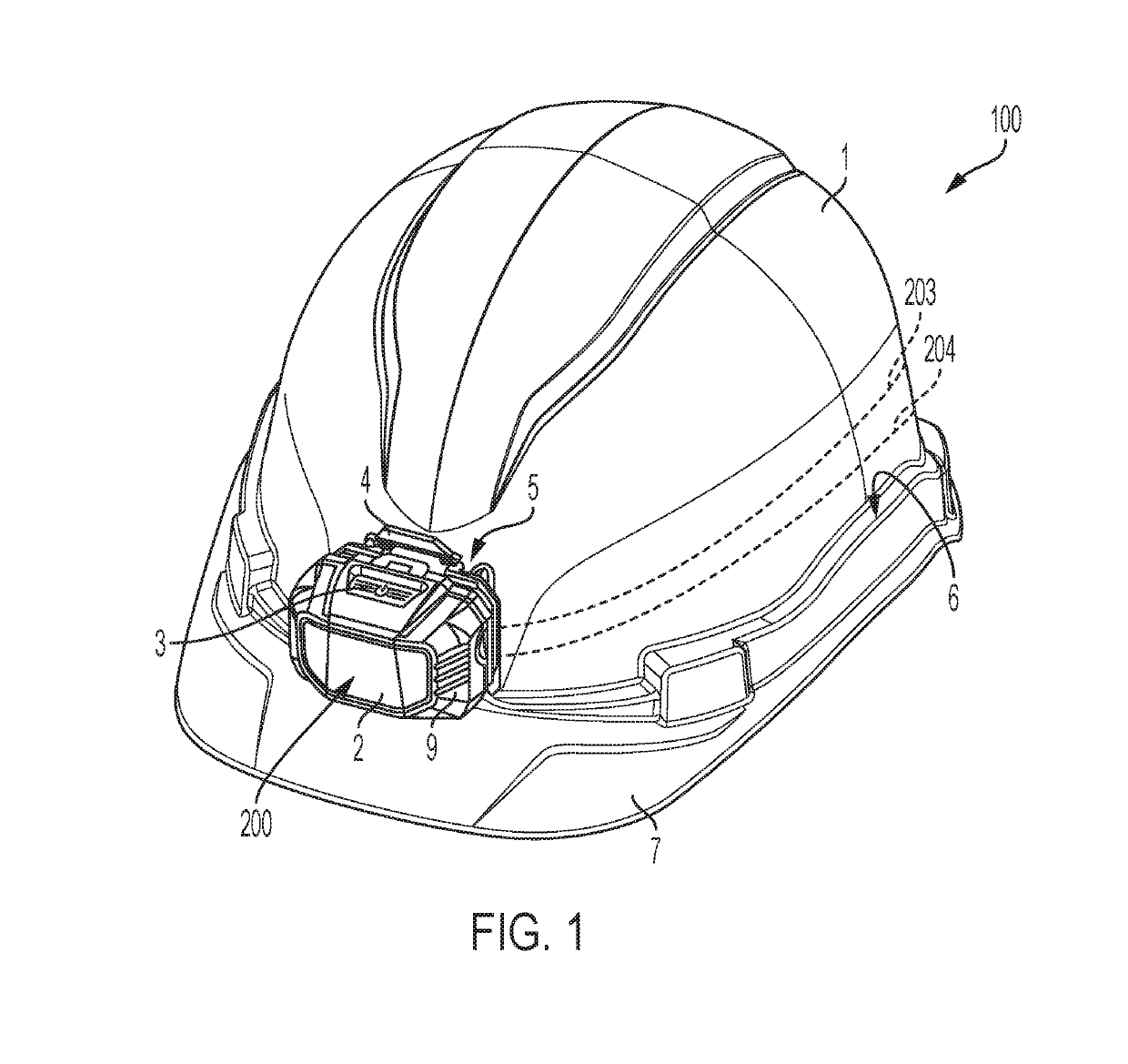
[0015]The present invention relates to the field of personal protection devices and, more particularly, safety helmets. The safety helmets in accordance with the disclosure include two mounts, one on either the front or back facing sides of the helmet, which permit connection of removable modules onto the helmet such as headlamps, cameras, speakers, larger capacity batteries, cellphones, and the like. In one embodiment, the helmet includes an integrated, non-removable power source and integrated electrical leads or conductors to a port for a removable device. In this way, the removable device such as a headlamp can be made lighter without sacrificing battery power output or electrical potential. The headlamp, which may include its own power source that is chargeable by the helmet, may be removed and used as a flashlight before being replaced onto the helmet for charging.

[0016]A safety helmet 100 in accordance with one embodiment of the present disclosure is shown in FIG. 1. The safe...


PUM


Abstract

A safety helmet includes an outer shell having a front receptacle disposed on a front side of the outer shell and a rear receptacle disposed on a rear side of the outer shell. A first accessory device having a first mating receptacle formed thereon is releasably mountable onto each of the front receptacle or the rear receptacle of the outer shell, and a second accessory device having a second mating receptacle formed thereon is releasably mountable onto each of the front receptacle or the rear receptacle of the outer shell.

Description

CROSS-REFERENCE TO RELATED APPLICATIONS[0001]This patent application claims the benefit of U.S. Provisional Patent Application No. 62 / 622,472, filed Jan. 26, 2018, and U.S. Provisional Patent Application No. 62 / 645,491, filed Mar. 20, 2018, each of which disclosure is incorporated herein by reference.BACKGROUND OF THE DISCLOSURE[0002]The present disclosure relates to personal protection devices and, more particularly, safety helmets for use to protect the wearer from falling objects. Such helmets are commonly also referred to as “hard hats.” Various types of safety helmets are commonly used in in several industries, many of which include mounted personal illumination devices commonly called headlamps, typically powered by a direct current power source (either replaceable or rechargeable chemical cells). In the simplest of such devices, the headlamp is permanently mounted to the safety helmet in a fixed orientation at the front of the safety helmet. In other such devices, a mounting ...

Claims


Application Information

Patent Timeline
IPC IPC(8): A42B3/04
CPCA42B3/0446A42B3/04
Inventor DESHPANDE, SHANTANUWONG, KINGSTON
Owner KLEIN TOOLS INC
Why Eureka
Eureka Blog
Learn More