Dual ballast cribber

Active Publication Date: 2019-11-21
SOTERRAN GRP LLC
View PDF0 Cites 0 Cited by
  • Summary
  • Abstract
  • Description
  • Claims
  • Application Information

AI Technical Summary

Benefits of technology

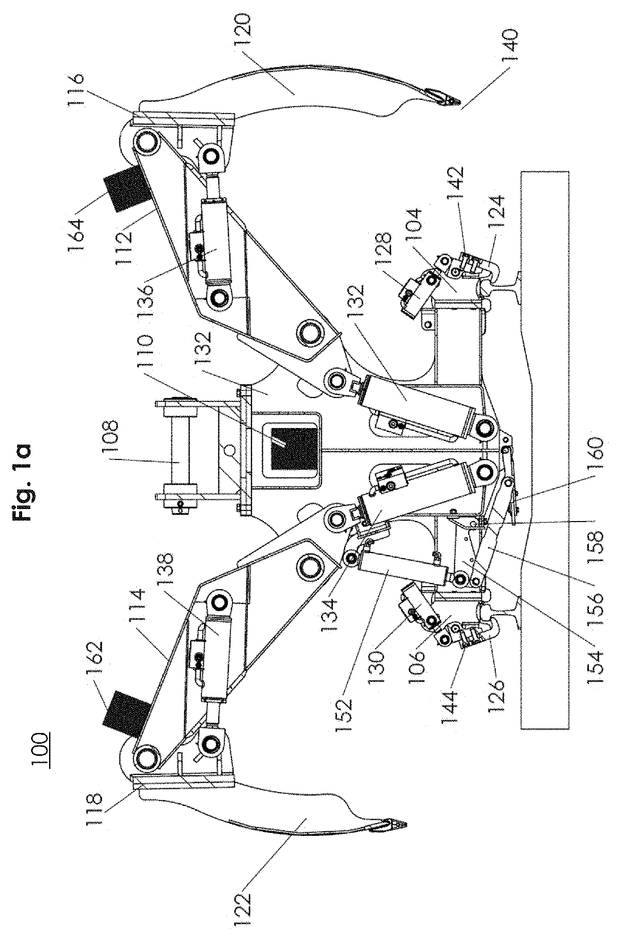
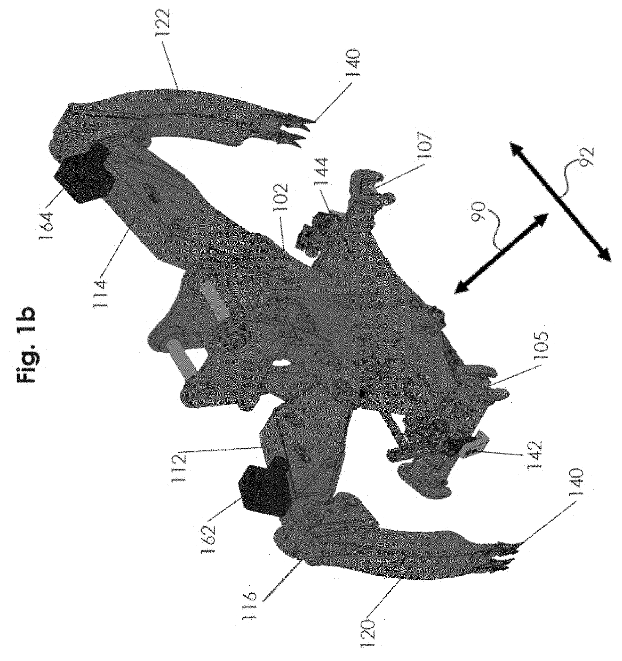
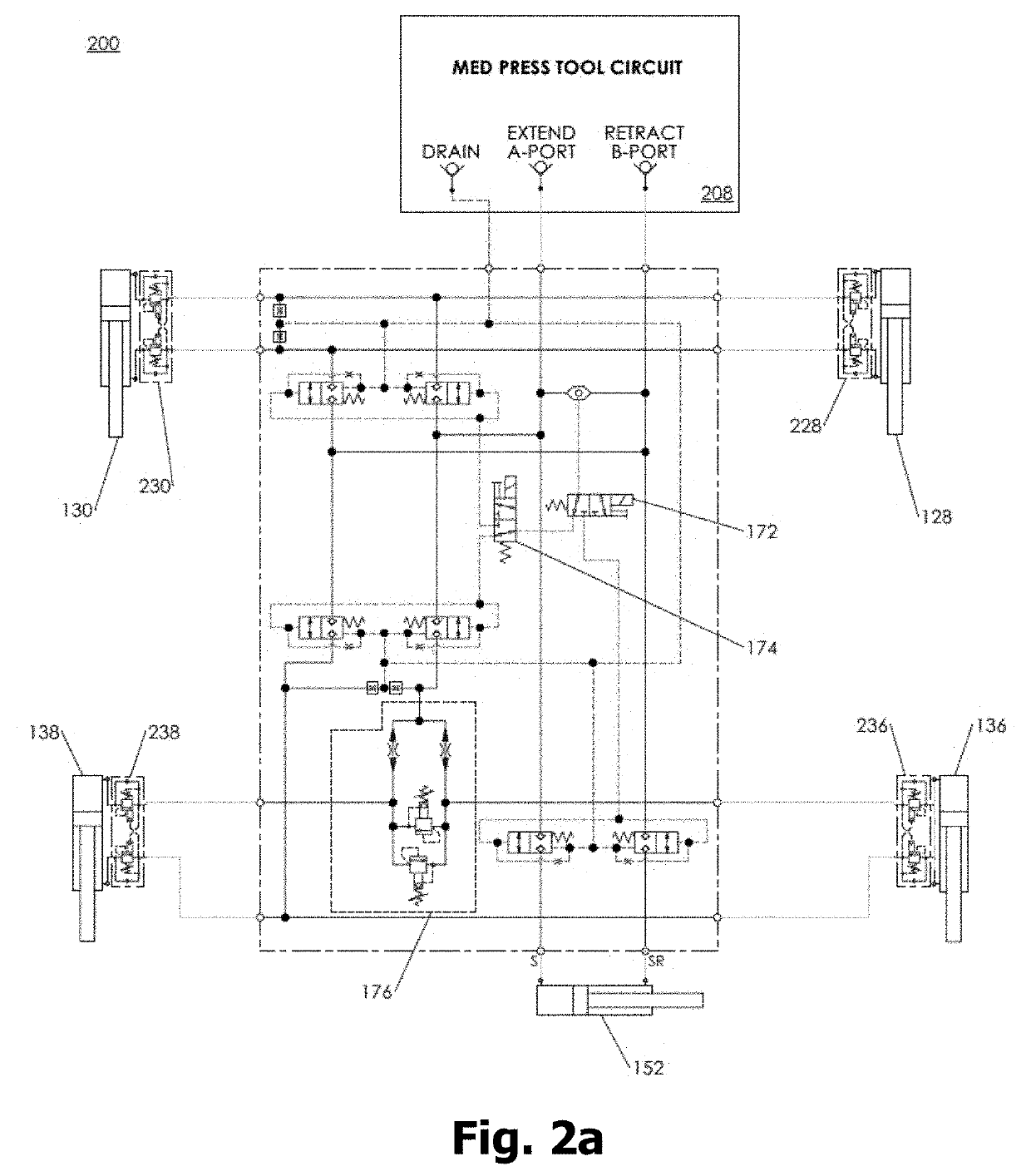
The patent describes a dual ballast cribber for removing fouled and cemented ballast from beneath a railway. The cribber has a central frame and two pivot arms that can be moved to position the cribber buckets. The cribber buckets can be moved between a digging position and a cleanout position. The cribber can be secured to the railway using clamps and hydraulic actuators. The method of using the cribber involves clamping it to the railway, using the pivot arms to position the buckets, and using the dig and cleanout circuits to remove the ballast. The technical effects of the invention include improved efficiency in removing ballast from beneath a railway and reduced damage to the railway from the removal process.

Problems solved by technology

A common problem associated with ballast is that it often becomes clogged due to improper draining.
The motion of a train over the railway having clogged or fouled ballast can cause water and mud to be brought from underneath the railway to the surface.
Cemented ballast can lead to problems with the railway, such as railway buckling or flooding.
These conventional methods present practical limitations and inefficiencies in preventing ballast from cementing or breaking apart and removing cemented ballast.
However, sledding requires site preparation, which includes lifting the rail and excavating underneath the rail to insert and pull the sled.
Moreover, sledding is inefficient (e.g. it requires additional time), as it requires off-rail equipment to pull the sled.
Finally, sledding is not seen as a solution for breaking apart cemented ballast.
Further, conventional methods that do allow for breaking apart of cemented ballast have practical limitations and inefficiencies.
It is also an off-rail method leading to increased inefficiency for placement and movement of the undercutter.
Using a conventional cribbing bucket is inefficient as is requires off-rail equipment and a significant amount of time to move and position the equipment between each rail tie.
Additionally, the cribbing bucket only removes fouled ballast from a single side at a time.
Further, it has the practical limitation of requiring an experienced operator to run the cribbing bucket without damaging the ties or rail of the railway.

Method used


Image

  • Dual ballast cribber
  • Dual ballast cribber
  • Dual ballast cribber

Examples


Embodiment Construction

[0035]The present invention now will be described more fully hereinafter with reference to the accompanying drawings, in which some, but not all, embodiments of the invention are shown. Indeed, this invention may be embodied in many different forms and should not be construed as limited to the embodiments set forth herein; rather, these embodiments are provided so that this disclosure will satisfy applicable legal requirements. Like numbers refer to like elements throughout. It is to be understood that this invention is not limited to the particular methodology and protocols described, as such may vary. It is also to be understood that the terminology used herein is for the purpose of describing particular embodiments only, and is not intended to limit the scope of the present invention.

[0036]Many modifications and other embodiments of the invention set forth herein will come to mind to one skilled in the art to which the invention pertains having the benefit of the teachings presen...


PUM


Abstract

A dual ballast cribber for on-rail operation for preventing and removing cemented ballast with minimal site preparation can include a central frame, a plurality of wheels, a first pivot arm, a second pivot arm, a first cribber bucket, a second cribber bucket, a first clamp, a second clamp, and a hydraulic system. The dual ballast cribber may perform a digging cycle in 2 minutes or less. Preferably the digging cycle is performed in 45 seconds or less.

Description

CROSS-REFERENCE TO RELATED APPLICATION[0001]The present application claims priority to and the benefit of the filing date of U.S. Provisional Patent Application No. 62 / 671,881, filed May 15, 2018, the disclosure of which is hereby incorporated by reference herein in its entirety for all purposes.BACKGROUND[0002]Many conventional railroads include crushed stone ballast underneath the rails and ties of the railway. The ballast functions to support the railway, provide vibration dampening, and facilitate drainage of water away from the railway. These functions extend the longevity of the railway. A common problem associated with ballast is that it often becomes clogged due to improper draining. The motion of a train over the railway having clogged or fouled ballast can cause water and mud to be brought from underneath the railway to the surface. This water and mud can then harden around the ballast in the consistency of concrete. This effect is sometimes referred to as cemented ballast...

Claims


Application Information

Patent Timeline
IPC IPC(8): E01B27/04
CPCE01B27/04
Inventor RAU, MICHAEL A.
Owner SOTERRAN GRP LLC
Why Eureka
Try Eureka