Electromagnetic valve

a technology of electromagnetic valves and plungers, applied in the direction of magnets, valve operating means/release devices, magnetic bodies, etc., can solve the problems of plungers tilting relative to fixed cores

Active Publication Date: 2020-03-05
CKD
View PDF0 Cites 1 Cited by
  • Summary
  • Abstract
  • Description
  • Claims
  • Application Information

AI Technical Summary

Benefits of technology

[0004]It is an objective of the present disclosure to provide an electromagnetic valve that limits magnetic saturation of the fixed core and tilting of the plunger relative to the fixed core.

Problems solved by technology

This may cause the plunger to tilt relative to the fixed core.
This difference may cause the plunger to further tilt relative to the fixed core.

Method used


Image

  • Electromagnetic valve
  • Electromagnetic valve
  • Electromagnetic valve

Examples


first embodiment

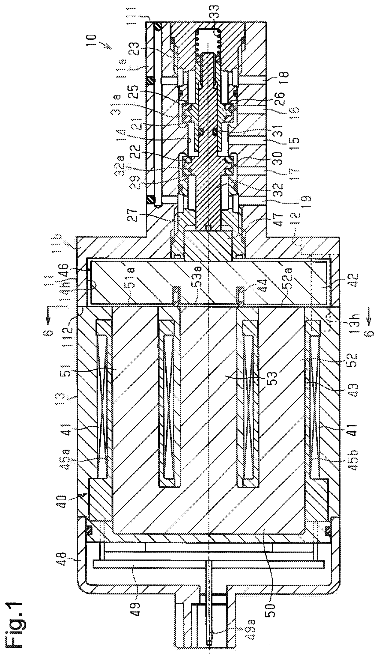
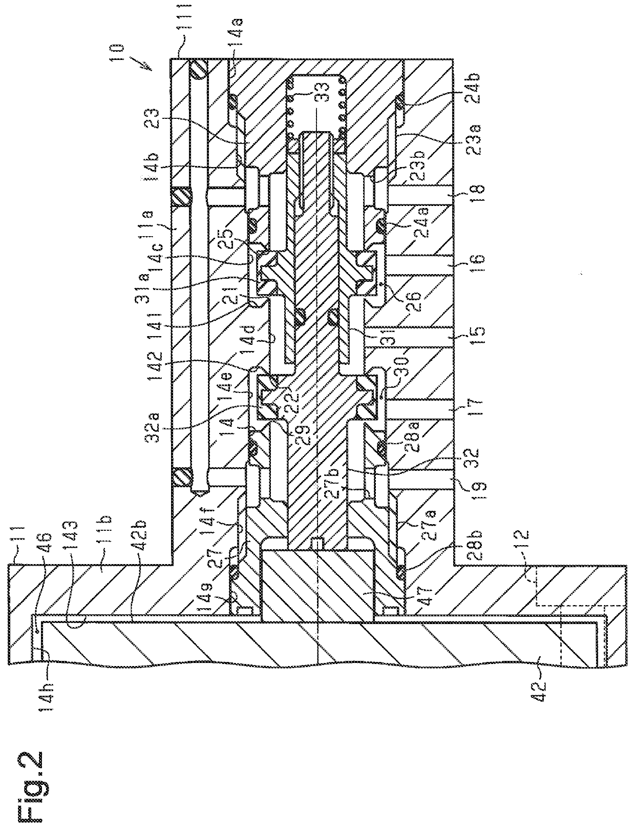
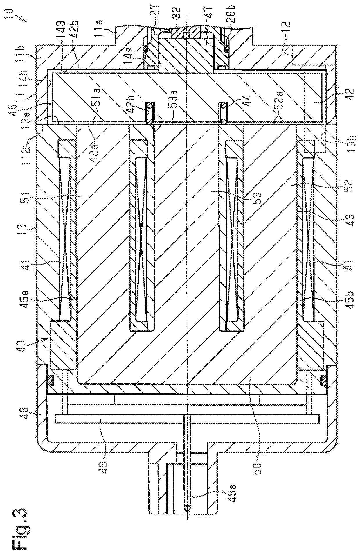
[0021]Referring to FIGS. 1 to 6, an electromagnetic valve according to a first embodiment is now described.

[0022]As shown in FIG. 1, an electromagnetic valve 10 includes a body 11 having a rectangular cross-section and a housing 13 having the shape of a rectangular block. The housing 13 is coupled to the body 11 by bolts 12. The body 11 and the housing 13 are made of a nonmagnetic material, such as plastic.

[0023]The body 11 has a main body section 11a, which is a peripheral wall having a rectangular cross-section, and a flange 11b, which projects from the main body section 11a. The long dashed short dashed lines in FIGS. 1 to 3 indicate the axis of the body 11. The flange 11b extends in a direction perpendicular to the axis from the end of the main body section 11a that is closer to the housing 13. The flange 11b has a rectangular outer edge. The housing 13 is coupled to the flange 11b by the bolts 12.

[0024]The body 11 has a first end face 111, which is a first end in the axial dire...

second embodiment

[0080]Referring to FIGS. 7 to 9, an electromagnetic valve according to a second embodiment is now described. In the description of the second embodiment, same reference numerals are given to those components that are the same as the corresponding components of the first embodiment. Such components will not be described in detail.

[0081]As shown in FIGS. 7 and 8, the base section 61a of each first U-shaped core 61 is bent such that the part connecting to the first leg section 61b is offset from the part connecting to the second leg section 61c toward the E-shaped cores 63. Thus, the first leg section 61b of the first U-shaped core 61 is offset from the second leg section 61c toward the E-shaped cores 63.

[0082]The base section 62a of each second U-shaped core 62 is bent such that the part connecting to the first leg section 62b is offset from the part connecting to the second leg section 62c toward the E-shaped cores 63. Thus, the first leg section 62b of the second U-shaped core 62 is...


PUM


Abstract

An electromagnetic valve has a solenoid, which includes a coil, a plunger, a fixed core, and a plunger spring. The fixed core is E-shaped and has a base, a first outer leg, a second outer leg, and a central leg. The first outer leg, the second outer leg, and the central leg extend from the base. The first outer leg has a first outer attraction surface configured to attract the plunger. The second outer leg has a second outer attraction surface configured to attract the plunger. The central leg has a central attraction surface configured to attract the plunger. The central attraction surface is larger in area than each of the first and second outer attraction surfaces.

Description

BACKGROUND1. Field[0001]The present disclosure relates to an electromagnetic valve including a solenoid having a plunger, which is moved by magnetic excitation of a coil.2. Description of Related Art[0002]The solenoid of an electromagnetic valve includes a coil, a plunger moved by magnetic excitation of the coil, a fixed core having an attraction surface for attracting the plunger, and a plunger spring, which urges the plunger away from the attraction surface of the fixed core. For example, Japanese Patent No. 5502240 discloses an electromagnetic valve having a U-shaped fixed core. The fixed core includes a base section and first and second leg sections extending parallel to each other from the base section. The distal end of the first leg section, which is opposite to the base section, includes an attraction surface for attracting the plunger. The distal end of the second leg section, which is opposite to the base section, includes an attraction surface for attracting the plunger. ...

Claims


Application Information

Patent Timeline
Patent Type & Authority Applications(United States)
IPC IPC(8): F16K31/06
CPCF16K31/0655F16K31/0651F16K31/0679H01F7/06F16K11/07F16K31/0613F16K31/0675F16K31/0627F16K31/0634H01F7/081H01F7/1638
Inventor ITOH, SHINJI
Owner CKD
Why Eureka
Try Eureka