Pulse transformer

a pulse transformer and transformer technology, applied in the field of pulse transformers, can solve the problems of insufficient inductance of pulse transformers, even enlarged gap, etc., and achieve the effect of suppressing magnetic saturation

Active Publication Date: 2015-03-26
TDK CORPARATION
View PDF5 Cites 27 Cited by
  • Summary
  • Abstract
  • Description
  • Claims
  • Application Information

AI Technical Summary

Benefits of technology

[0021]According to the present invention, a gap, created between contact surfaces by roughly grinding the surfaces intentionally (specifically in such a manner that the inductance becomes equal to or higher than 350 μH under the bias current of 8 mA, functions as a minute magnetic gap that suppresses magnetic saturation. Therefore, even when the pulse transformer has a small size of approximately 3.3 mm×3.3 mm×2.7 mm, the pulse transformer can still achieve the inductance of 350 μH or higher under the bias current of 0 mA to 8 mA.

Problems solved by technology

This is because grinding is not performed on the plate core and the drum core, and therefore there is a gap created therebetween, and moreover this gap is even enlarged by the thickness of the adhesive.
However, the technique in Japanese Patent Application Laid-open No. 2009-302321 has a problem that, while the pulse transformer with a size (4.5 mm×3.2 mm×2.9 mm) described in Japanese Patent Application Laid-open No. 2009-302321 can achieve the inductance that satisfies the above standard value, the pulse transformer with a smaller size (for example, 3.3 mm×3.3 mm×2.7 mm) cannot obtain a sufficient inductance particularly when the bias current is high.
In contrast to this, in a pulse transformer with a smaller size of 3.3 mm×3.3 mm×2.7 mm, although assuming that the need for adhesion is ignored, and thus an adhesive filling groove is not provided, it is still difficult to increase the cross-sectional area of the magnetic path in the contact-surface portion to such a degree as to obtain an inductance initial value large enough to compensate for a decrease in the inductance due to magnetic saturation.

Method used


Image

  • Pulse transformer
  • Pulse transformer
  • Pulse transformer

Examples


Embodiment Construction

[0035]Preferred embodiments of the present invention will now be explained in detail, with reference to the drawings.

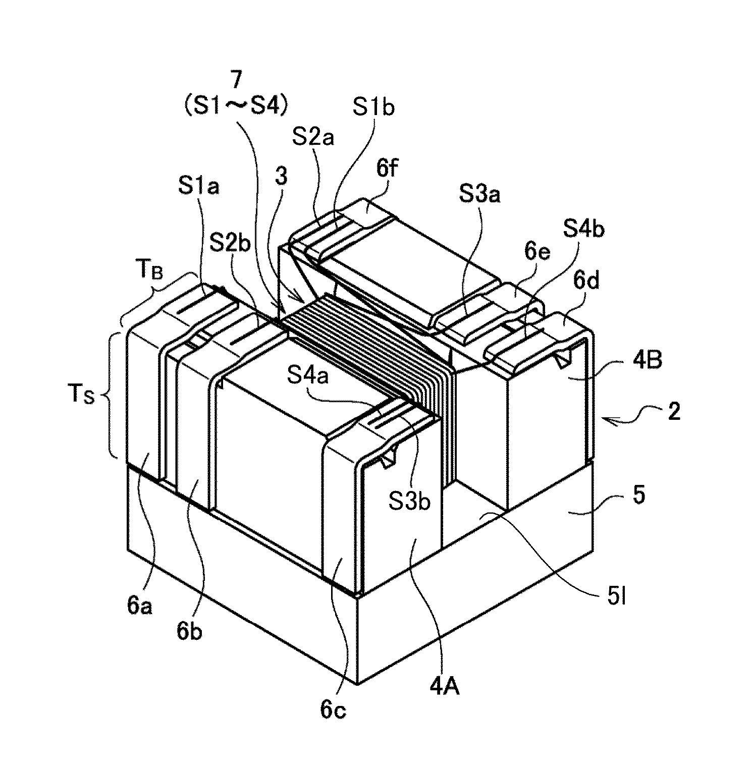
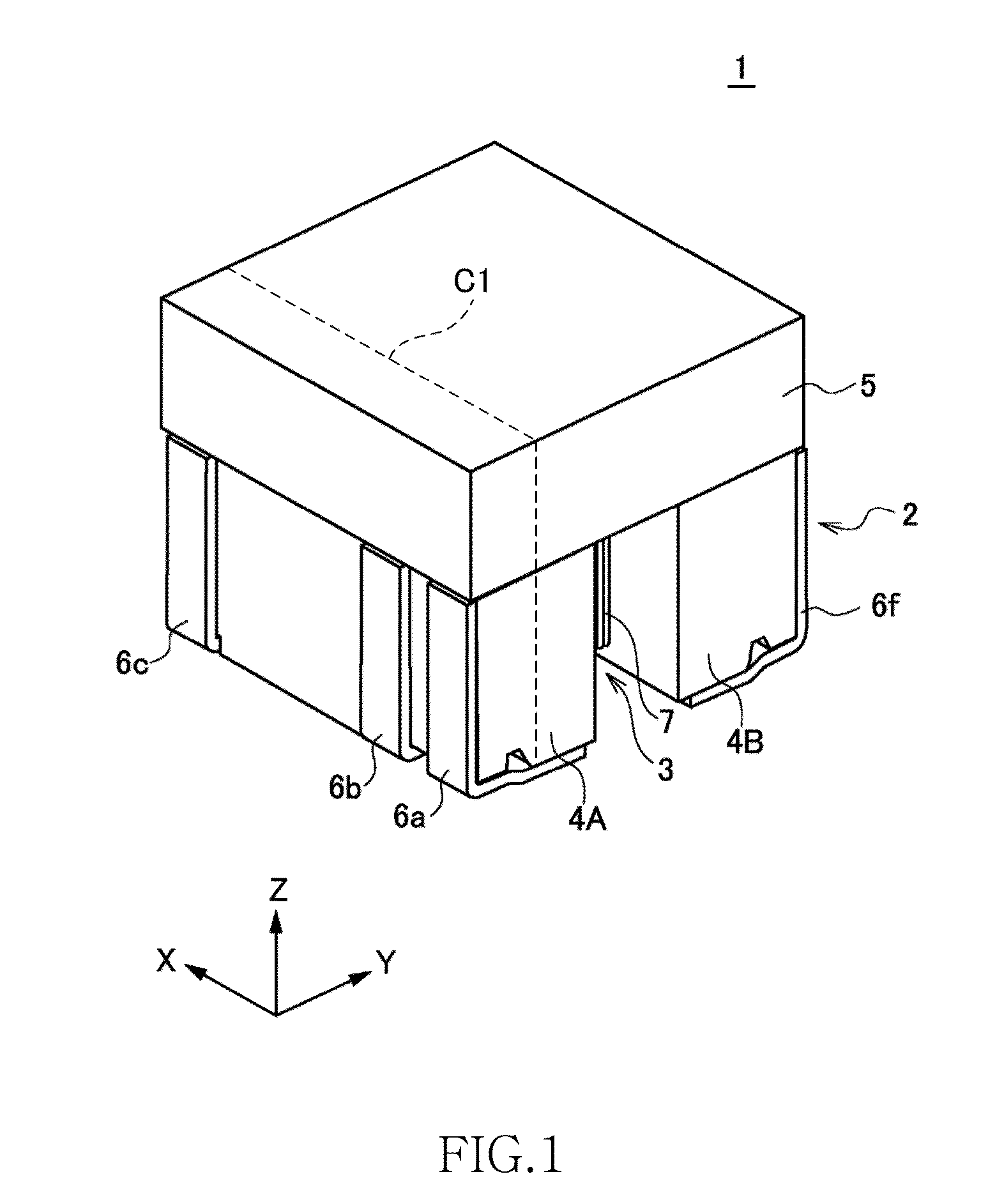
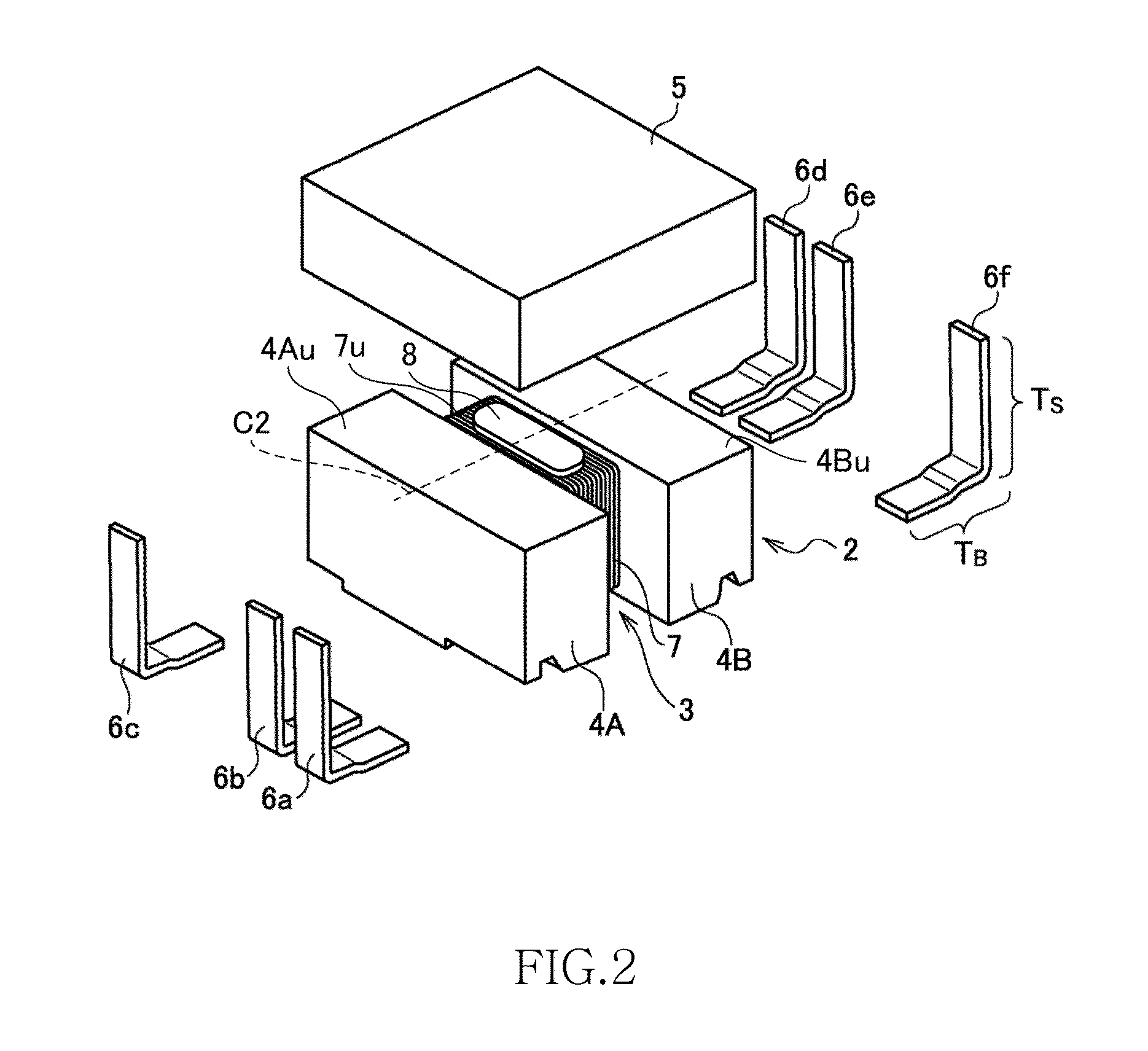
[0036]As shown in FIGS. 1 to 5, a pulse transformer 1 according to the present embodiment includes a drum core 2, a plate core 5, six terminal fittings 6a to 6f, and a coil 7 that is constituted by four wires S1 to S4 (first to fourth fires) that are wound around the drum core 2. Although not particularly limited thereto, the size of the pulse transformer 1 in the X-direction, Y-direction, and Z-direction is 3.3 mm×3.3 mm×2.7 mm, for example.

[0037]The drum core 2 is made of a magnetic material such as Ni—Zn-based ferrite, and includes a winding core portion 3 on which the coil 7 is wound, and first and second flange portions 4A and 4E that are provided at both ends of the winding core portion 3 in the Y-direction. The plate core 5 is also made of a magnetic material such as Ni—Zn-based ferrite, and is arranged such that a first portion 51a (FIG. 3) of a bottom surface...


PUM

PropertyMeasurementUnit
bias currentaaaaaaaaaa
inductanceaaaaaaaaaa
gap lengthaaaaaaaaaa

Abstract

Disclosed herein is a pulse transformer that includes a drum core having a winding core portion and first and second flange portions, a plate core connected to the first and second flange portions, and a plurality of wires that are wound around the winding core portion. The first and second flange portions and the plate core are ground such that an inductance of the pulse transformer is 350 μH or more when a bias current of 8 mA is applied to the wires.

Description

BACKGROUND OF THE INVENTION[0001]1. Field of the Invention[0002]The present invention relates to a pulse transformer, and more particularly relates to a surface-mount pulse transformer configured by using a drum core and a plate core.[0003]2. Description of Related Art[0004]When a device such as a personal computer is connected to a network such as a LAN or a telephone network, it is necessary to protect the device from the entry of ESD (Electrostatic Discharge) and high voltage via a cable. Therefore, a pulse transformer is used in a connector that constitutes a connection point between the cable and the device.[0005]In recent years, as the pulse transformer described above, a surface-mount pulse transformer suitable for high-density mounting is frequently used. The surface-mount, pulse transformer is configured by using a drum core and a plate core. The drum core is a magnetic body, and includes a winding core portion, and a pair of flange portions that are formed at both ends o...

Claims


Application Information

Patent Timeline
Patent Type & Authority Applications(United States)
IPC IPC(8): H01F27/26H01F27/28
CPCH01F27/2823H01F27/263H01F19/08H01F2019/085
Inventor TAKAGI, NOBUOTSUCHIDA, SETUMIKOGAMI, TASUKUSUTO, TOMONAO
Owner TDK CORPARATION
Why Eureka
Try Eureka