Supercharge Your Innovation With Domain-Expert AI Agents!

Fluid machine

a technology of fluid machine and compressor, which is applied in the direction of machines/engines, rotary/oscillating piston pump components, liquid fuel engines, etc., can solve the problems of inability to change, the internal volume of the conventional screw expander or screw compressor is mostly fixed and inconvenient to use, and the expansioner or the compressor may not achieve optimal usage efficiency

Active Publication Date: 2020-03-12
FUSHENG IND CO LTD
View PDF0 Cites 3 Cited by
  • Summary
  • Abstract
  • Description
  • Claims
  • Application Information

AI Technical Summary

Benefits of technology

The fluid machine in this patent allows for adjustment of its internal volume ratio by controlling the positions of various parts. This is possible through the use of slides and screw rotors that can be controlled independently or simultaneously to meet different practical needs.

Problems solved by technology

The internal volume of the conventional screw expanders or screw compressors is mostly fixed and unchangeable.
In addition, because the internal volume ratio of the conventional screw expanders or the screw compressors is fixed and unchangeable, under different usages, the expanders or the compressors may not achieve optimal usage efficiency.

Method used


Image

  • Fluid machine
  • Fluid machine
  • Fluid machine

Examples


first embodiment

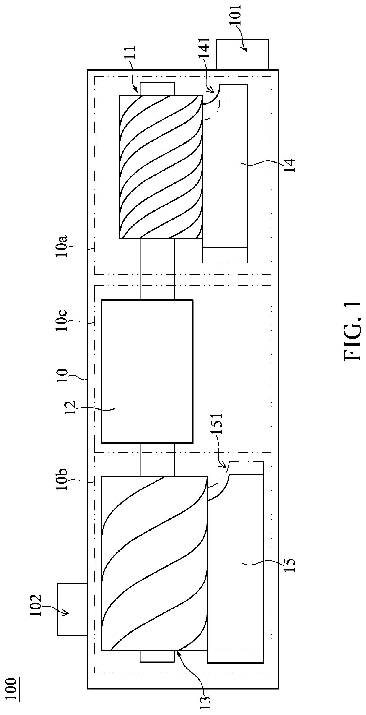
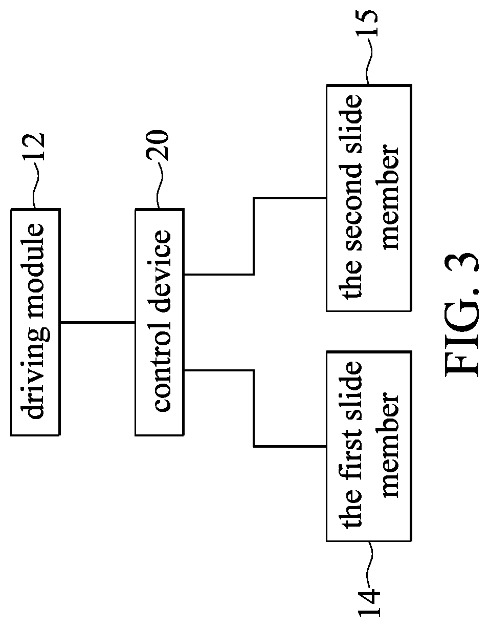
[0019]Referring to FIG. 1 to FIG. 3, a first embodiment of the present disclosure provides a fluid machine 100 including a main body 10, two first screw rotors 11, a driving module 12, two second screw rotors 13, a first slide member 14, a second slide member 15, and a control device 20. The two first screw rotors 11, the driving module 12, the two second screw rotors 13, the first slide member 14, and the second slide member 15 are arranged in the main body 10. The control device 20 is electrically connected to the driving module 12 to control the driving module 12. The control device 20 can be integrated and arranged in a computer device or other kinds of processors of the fluid machine 100, but the present disclosure is not limited thereto.

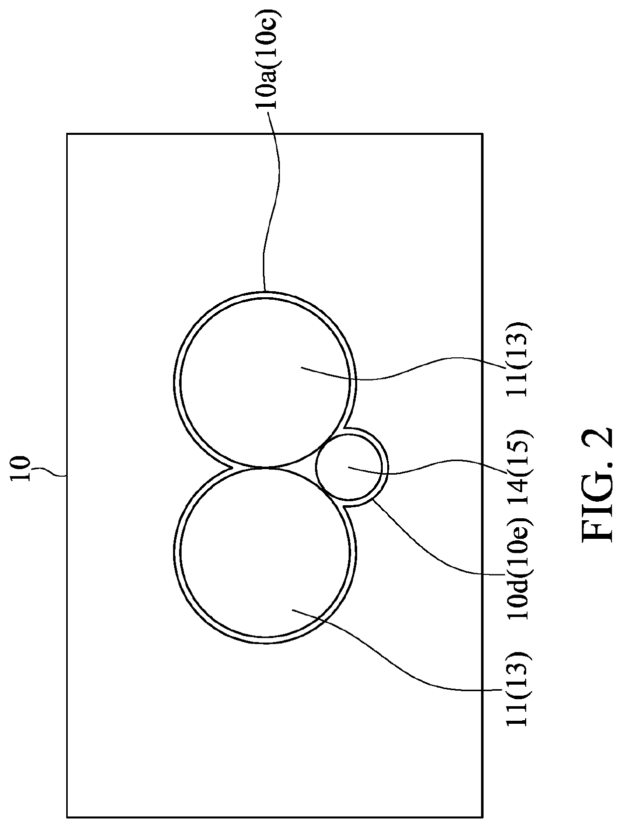
[0020]Referring to FIG. 1 and FIG. 2, the main body 10 is internally separated into a first chamber 10a, a second chamber 10b, a drive chamber 10c, a first auxiliary chamber 10d, and a second auxiliary chamber 10e. The first chamber 10a, the se...

second embodiment

[0032]Referring to FIG. 4 and FIG. 5, FIG. 4 is a side view of a fluid machine of present disclosure according to a second embodiment of the present disclosure, and FIG. 5 is a block diagram of the fluid machine of the present disclosure according to the second embodiment of the present disclosure. As shown in FIG. 1 to FIG. 5, the main difference between the present embodiment and the previous embodiment is that the fluid machine 100 can also include a first pressure measuring unit 30 and a second pressure measuring unit 40, wherein the fluid machine 100 can only include the first pressure measuring unit 30 or the second pressure measuring unit 40, but the present disclosure is not limited thereto.

[0033]A first pressure measuring unit 30 is arranged near the first chamber 10a and the first auxiliary chamber 10d, and the first pressure measuring unit 30 is configured to measure the fluid pressure between the first slide member 14 and the two first screw rotors 11. The first pressure...


PUM


Abstract

A fluid machine includes a main body, two first screw rotors, two second screw rotors, a driving module, a first slide member and a second slide member. The two first screw rotors are meshingly engaged with each other. The two second screw rotors are meshingly engaged with each other. Two first screw rotors are arranged in the first chamber of the main body. Two second screw rotors are arranged in the second chamber of the main body. The driving module is arranged in the drive chamber of the main body. The first slide member can move relative to the two first screw rotors. The second slide member can move relative to the two second screw rotors. A fluid entering the main body exits after being compressed or expanded by the two first screw rotors and the two second screw rotors.

Description

CROSS-REFERENCE TO RELATED PATENT APPLICATION[0001]This application claims the benefit of priority to Taiwan Patent Application No. 107132066, filed on Sep. 12, 2018. The entire content of the above identified application is incorporated herein by reference.[0002]Some references, which may include patents, patent applications and various publications, may be cited and discussed in the description of this disclosure. The citation and / or discussion of such references is provided merely to clarify the description of the present disclosure and is not an admission that any such reference is “prior art” to the disclosure described herein. All references cited and discussed in this specification are incorporated herein by reference in their entireties and to the same extent as if each reference was individually incorporated by reference.FIELD OF THE DISCLOSURE[0003]The present disclosure relates to a fluid machine, and more particularly to a fluid machine having double-segment screw rotors...

Claims


Application Information

Patent Timeline
Patent Type & Authority Applications(United States)
IPC IPC(8): F04C18/16F04C23/00
CPCF05B2240/20F04C18/16F04C23/001F04C28/18F04C29/00F04C28/12
Inventor LIU, YAO-CHUNG
Owner FUSHENG IND CO LTD
Features
  • R&D
  • Intellectual Property
  • Life Sciences
  • Materials
  • Tech Scout
  • Unparalleled Data Quality
  • Higher Quality Content
  • 60% Fewer Hallucinations
Learn More