Embedded Fiber Optic Sensor System

a fiber optic sensor and fiber optic technology, applied in the field of vehicle sensor systems, can solve the problems that the data currently collected may not be as useful as desired in certain situations

Active Publication Date: 2020-07-02
THE BOEING CO
View PDF0 Cites 3 Cited by
  • Summary
  • Abstract
  • Description
  • Claims
  • Application Information

AI Technical Summary

Problems solved by technology

However, the data currently collected may not be as useful as desired in cert

Method used


Image

  • Embedded Fiber Optic Sensor System
  • Embedded Fiber Optic Sensor System
  • Embedded Fiber Optic Sensor System

Examples


Embodiment Construction

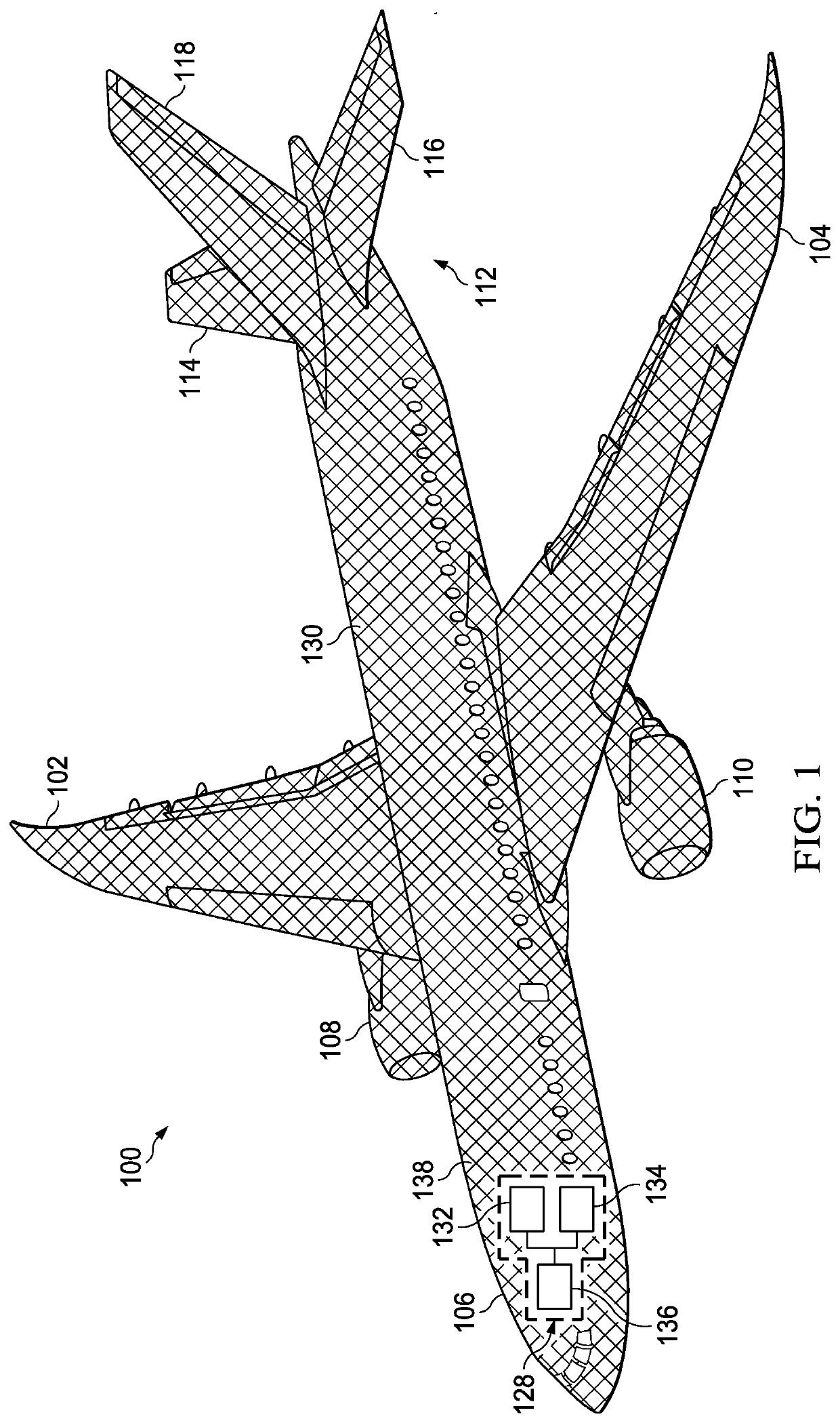
[0024]The illustrative embodiments recognize and take into account one or more different considerations. For example, the illustrative embodiments recognize and take into account that the data provided by currently used sensor systems in aircraft may not be as sufficient as desired. For example, the data currently obtained may not enable performing maintenance in a manner that reduces aircraft on ground (AOG) situations as much. For example, the illustrative embodiments recognize and take into account that it would be desirable to detect events that can cause nonconformances. The illustrative embodiments recognize and take in account that it would be desirable to detect events such as an impact, a vibration, a strain, a stress, a temperature, a turbulence, or other events that can cause undesired amounts of wear or nonconformances on an aircraft.

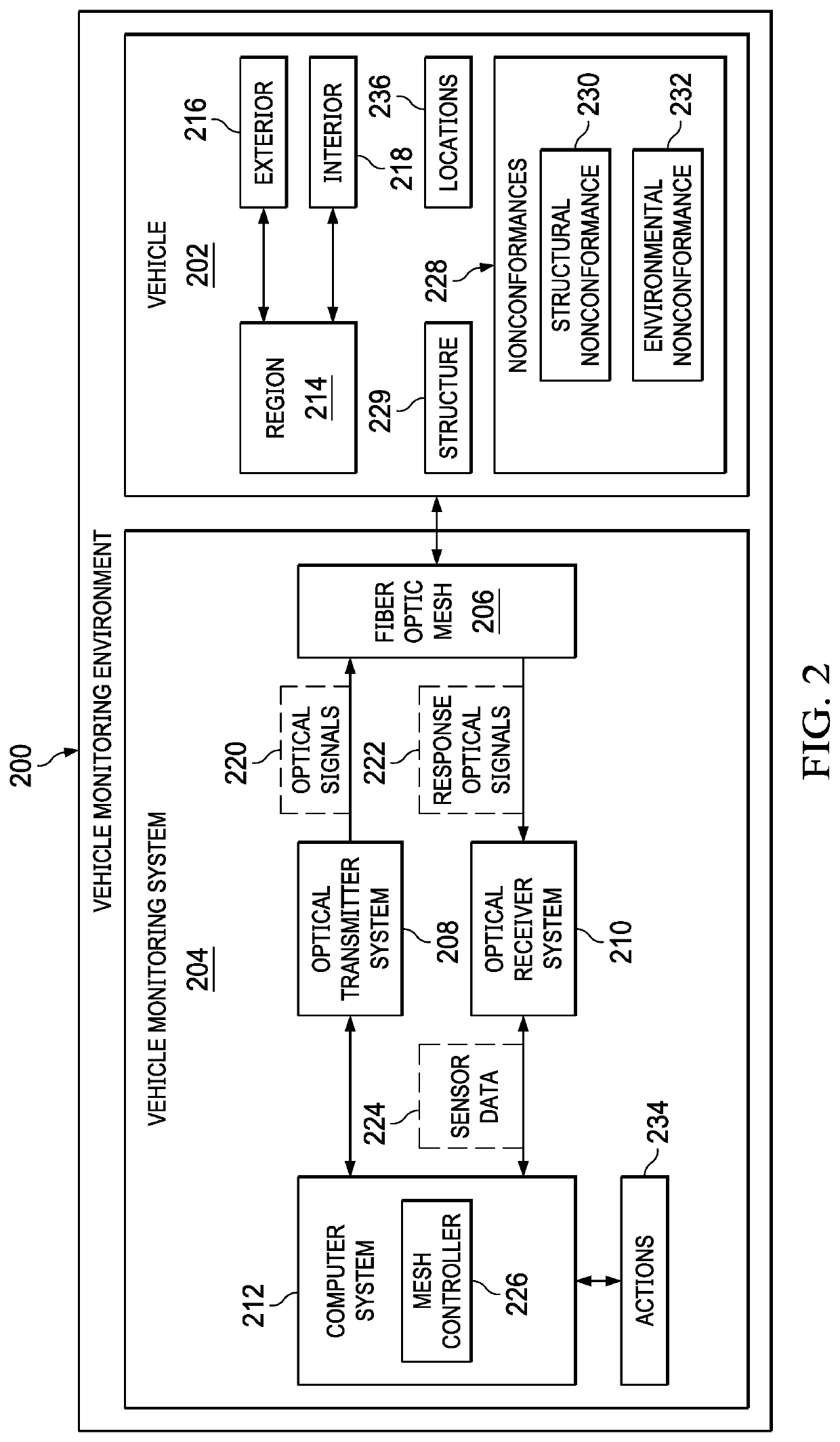
[0025]Thus, the illustrative embodiments provide a method, an apparatus, and a system for monitoring a vehicle such as an aircraft. In one ...


PUM


Abstract

A method, apparatus, and system for monitoring a vehicle. Optical signals are sent into a fiber optic mesh covering a region of the vehicle. Response optical signals occurring in response to optical signals sent into the fiber optic mesh are detected. Sensor data is generated from the response optical signals detected. A determination is made as to whether a group of nonconformances is present in the vehicle using the sensor data. A group of actions is performed when the group of nonconformances is present.

Description

BACKGROUND INFORMATION1. Field[0001]The present disclosure relates generally to sensor systems for vehicles, and in particular, to fiber object sensor systems for monitoring vehicles.2. Background[0002]Predicting when maintenance is needed can be performed using flight data in flight logs from flights of the aircraft. These flight data include performance data (e.g., fuel use), temperature, engine speed, cabin pressure, altitude, and other information about the flight of an aircraft. This information can be analyzed to predict when maintenance is needed. However, the data currently collected may not be as useful as desired in certain situations, such as for example, to reduce aircraft on ground situations.[0003]It would be desirable to have a method and apparatus that take into account at least some of the issues discussed above, as well as other possible issues. For example, it would be desirable to have a method and apparatus that overcome a technical problem with determining when...

Claims


Application Information

Patent Timeline
IPC IPC(8): H04B10/80H04B10/25H04L29/08H04B10/50H04B10/66B64D45/00B64F5/40G07C5/08
CPCH04B10/66H04B10/50H04B10/80B64D45/00B64D2045/009H04L67/12G07C5/0808H04B10/25B64D2045/0085B64F5/40B64D43/00G01M5/0016G01M5/0033G01M5/0041G01M5/0091
Inventor LAUGHLIN, BRIAN DALE
Owner THE BOEING CO
Why Eureka
Try Eureka