

Vaporization device having a wick and coil assembly
a technology of vaporizer and wick, which is applied in the direction of ohmic-resistance heating, tobacco, electrical equipment, etc., can solve the problems of wick that dries out or is overheated by the heating element, poor taste, and degrade the chemical composition of the e-liquid
- Summary
- Abstract
- Description
- Claims
- Application Information
AI Technical Summary
Benefits of technology
Problems solved by technology
Method used
Image


Examples
Embodiment Construction
[0019]The following detailed embodiments presented herein are for illustrative purposes. That is, these detailed embodiments are intended to be exemplary of the present invention for the purposes of providing and aiding a person skilled in the pertinent art to readily understand how to make and use of the present invention.
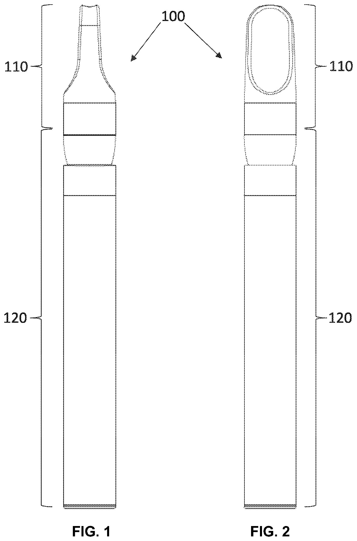
[0020]A first embodiment of a vaporization device 100 of the present invention is shown in FIGS. 1 and 2. Externally viewed, the vaporization device 100 comprises a mouthpiece 110 attached to an end of a body 120. The mouthpiece 110 includes an aperture 130 (see FIG. 3) therethrough for a user to draw on the vaporization device 100. The aperture 130 is fluidly connected to an interior volume of a vent tube 190 shown in FIGS. 3-5. Additional apertures (not shown) are disposed elsewhere on the body 120 to allow ambient air to enter the body 120 in response to the user's draw.
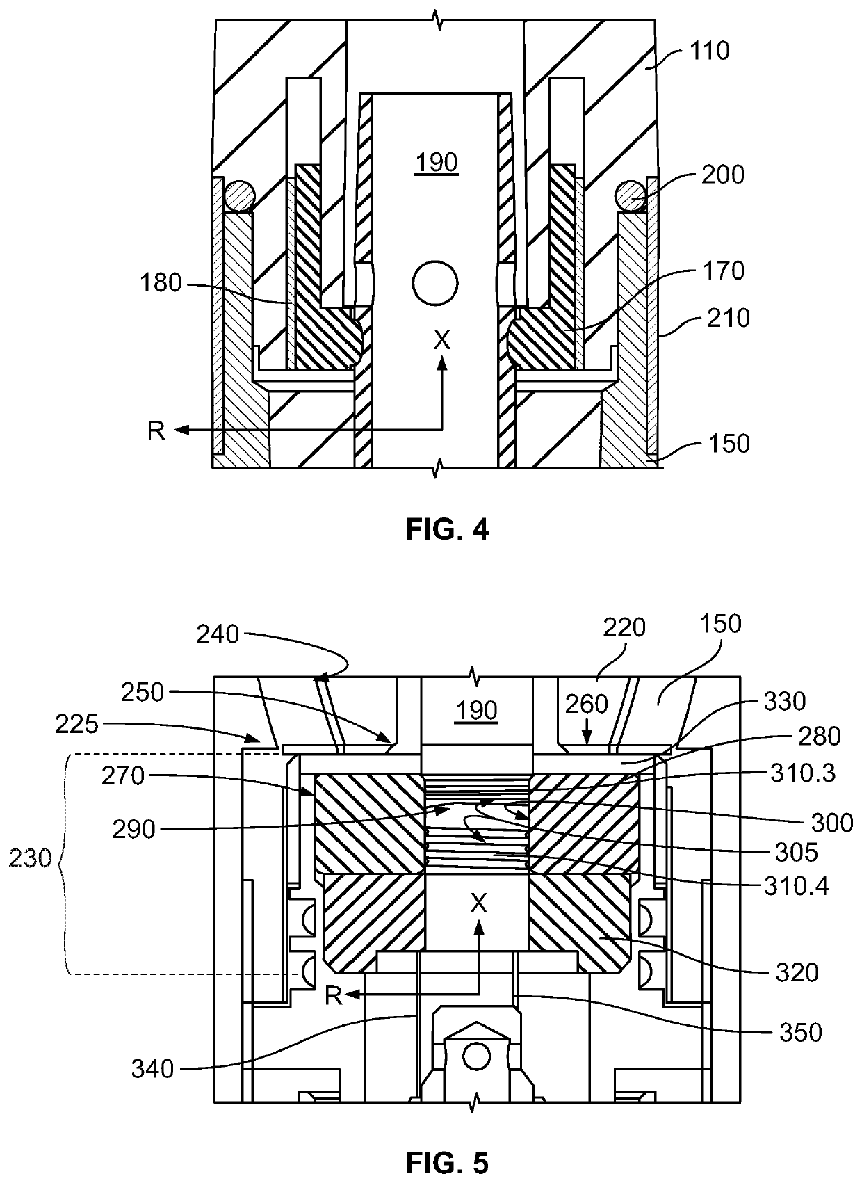
[0021]Referring to FIG. 3, in cross-section additional components of the first embodiment of...
PUM
 Abstract
Description
Claims
Application Information