Stapling device with articulating tool assembly

a technology of articulating tool and stapling device, which is applied in the field of articulating tool assembly, can solve problems such as unstable tool assembly, and achieve the effect of increasing the bending radius of the flexible body

Active Publication Date: 2020-10-08
TYCO HEALTHCARE GRP LP
View PDF0 Cites 0 Cited by
  • Summary
  • Abstract
  • Description
  • Claims
  • Application Information

AI Technical Summary

Benefits of technology

[0007]One aspect of the disclosure is directed to a surgical stapling device including a body portion, a mounting assembly, a drive assembly, an articulation assembly, and a gate assembly. The housing includes a proximal portion and a distal portion. The mounting assembly is pivotably supported on the distal portion of the housing about a pivot axis and movable between a non-articulated position and an articulated position. The drive assembly includes a flexible body having a working end. The drive assembly is movable within the housing from a retracted position to an advanced position. The articulation assembly includes an active articulation link having a proximal portion and a distal portion that is coupled to the mounting assembly. The active articulation link is movable between a retracted position and an advanced position to pivot the mounting assembly about the pivot axis. The gate assembly defines a channel that receives the flexible body of the drive assembly, wherein the active articulation link is positioned to engage the gate assembly when the active articulation link moves between its retracted and advanced positions to move the gate assembly to a position to increase the bending radius of the flexible body of the drive assembly.

Problems solved by technology

In known stapling devices, the tool assembly is unstable when the tool assembly is in a non-articulated position, i.e., the position in which a longitudinal axis of the tool assembly is aligned with a longitudinal axis the elongate body.

Method used


Image

  • Stapling device with articulating tool assembly
  • Stapling device with articulating tool assembly
  • Stapling device with articulating tool assembly

Examples


Embodiment Construction

[0049]The presently disclosed device will now be described in detail with reference to the drawings in which like reference numerals designate identical or corresponding elements in each of the several views. However, it is to be understood that the disclosed embodiments are merely exemplary of the disclosure and may be embodied in various forms. Well-known functions or constructions are not described in detail to avoid obscuring the present disclosure in unnecessary detail. Therefore, specific structural and functional details disclosed herein are not to be interpreted as limiting, but merely as a basis for the claims and as a representative basis for teaching one skilled in the art to variously employ the present disclosure in virtually any appropriately detailed structure.

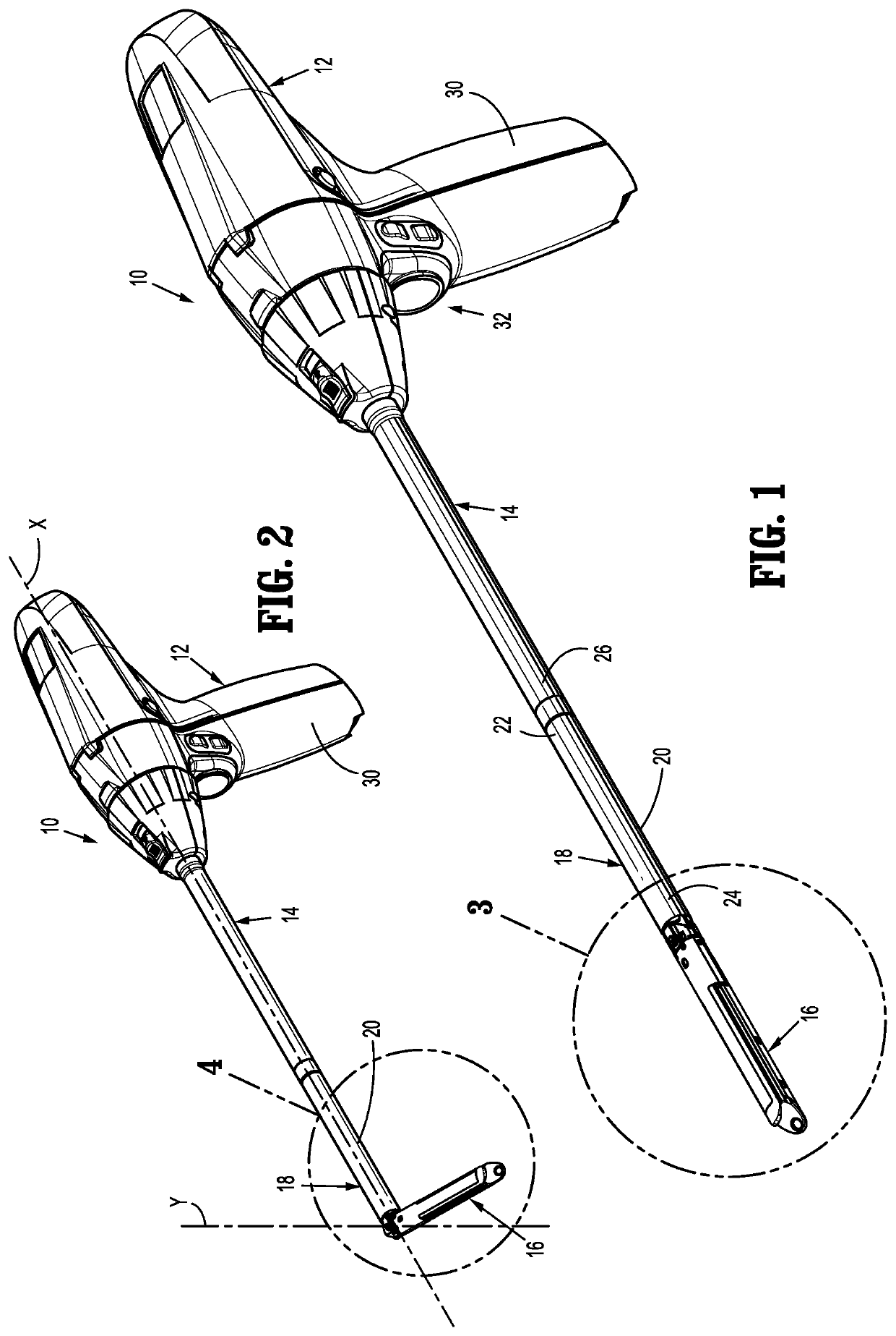
[0050]In this description, the term “proximal” is used generally to refer to that portion of the device that is closer to a clinician, while the term “distal” is used generally to refer to that portion of the de...


PUM


Abstract

A surgical stapling device includes a mounting assembly that is pivotably supported on a distal portion of a housing about a pivot axis and movable between a non-articulated position and an articulated position. A drive assembly includes a flexible body having a working end and an articulation assembly includes an active articulation link that is coupled to the mounting assembly and movable between a retracted position and an advanced position to pivot the mounting assembly about the pivot axis. A gate assembly defines a channel that receives the flexible body of the drive assembly. The active articulation link is positioned to engage the gate assembly when the active articulation link moves between its retracted and advanced positions to move the gate assembly to a position to increase the bending radius of the flexible body of the drive assembly.

Description

CROSS-REFERENCE TO RELATED APPLICATIONS[0001]This application claims the benefit of and priority to U.S. Provisional Patent Application Ser. No. 62 / 828,217 filed Apr. 2, 2019, the entire disclosure of which is incorporated by reference herein.BACKGROUND1. Technical Description[0002]The present disclosure is directed to surgical stapling devices, and more particularly, to surgical stapling devices with tool assemblies that are supported on the stapling device for articulation.2. Background of Related Art[0003]Surgical stapling devices configured for endoscopic or laparoscopic use include an elongate body having a proximal portion and a distal portion, and a tool assembly supported on the distal portion of the elongate body. Typically, the tool assembly is supported by a pivot member that facilitates articulation of the tool assembly in relation to the elongate body. In some stapling devices, the tool assembly is limited to about 45 degrees of articulation about the pivot member in on...

Claims


Application Information

Patent Timeline
Patent Type & Authority Applications(United States)
IPC IPC(8): A61B17/072
CPCA61B17/072A61B2017/07271A61B2017/07257A61B2017/0053A61B2017/2927A61B2017/07214A61B2017/00367A61B2017/00477A61B17/07207A61B2017/07285A61B2017/00473
Inventor KOSTRZEWSKI, STANISLAWBEARDSLEY, JOHN
Owner TYCO HEALTHCARE GRP LP
Why Eureka
Try Eureka