
Motorcycle locking system

a technology for locking systems and motorcycles, applied in the direction of anti-theft cycle devices, cycle equipments, bicycle stands, etc., can solve the problems of many locks not being strong or hefty enough to keep a thief, and the current model is high performan

Active Publication Date: 2020-10-22
ERRICKSON JR MICHAEL W
View PDF0 Cites 1 Cited by
  • Summary
  • Abstract
  • Description
  • Claims
  • Application Information

AI Technical Summary

Benefits of technology

The present invention is a motorcycle locking system that solves the limitations and disadvantages of current motorcycle locks. It is designed to secure the wheel of a motorcycle and the motorcycle itself. The system includes a locking housing with a back wall, dual sidewalls, and a bottom floor that partially circumscribes a slotted space for receiving the wheel of a motorcycle. A locking base is provided that has rail members that slidably receive the lateral sections of the bottom floor to secure the locking housing to the base. An elongated cycle lock is provided to secure the wheel and the motorcycle within the locking housing. The invention has various features and advantages, which are described in detail below.

Problems solved by technology

Motorcycles, and especially current models, are high performance, expensive vehicles.
As a result, motorcycle owners are constantly concerned about the safety of their vehicles, including the potential for theft when cycles are parked or otherwise left unattended.
While there have been a number of attempts to provide effective motorcycle locks and locking systems, most have significant drawbacks.
For example, many locks are just not strong or hefty enough to keep a thief from easily removing the lock or merely absconding with both the cycle and the lock.
Other locks and locking devices have a number of components and thus are quite complex, such that they are not only difficult and cumbersome to operate, but are also expensive to manufacture.

Method used


Image

  • Motorcycle locking system
  • Motorcycle locking system
  • Motorcycle locking system

Examples


Embodiment Construction

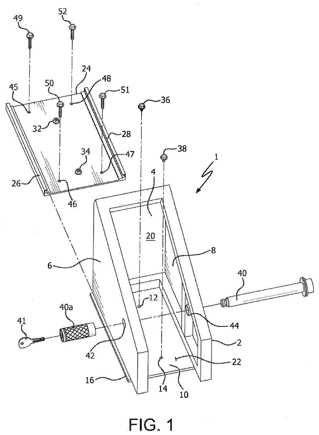
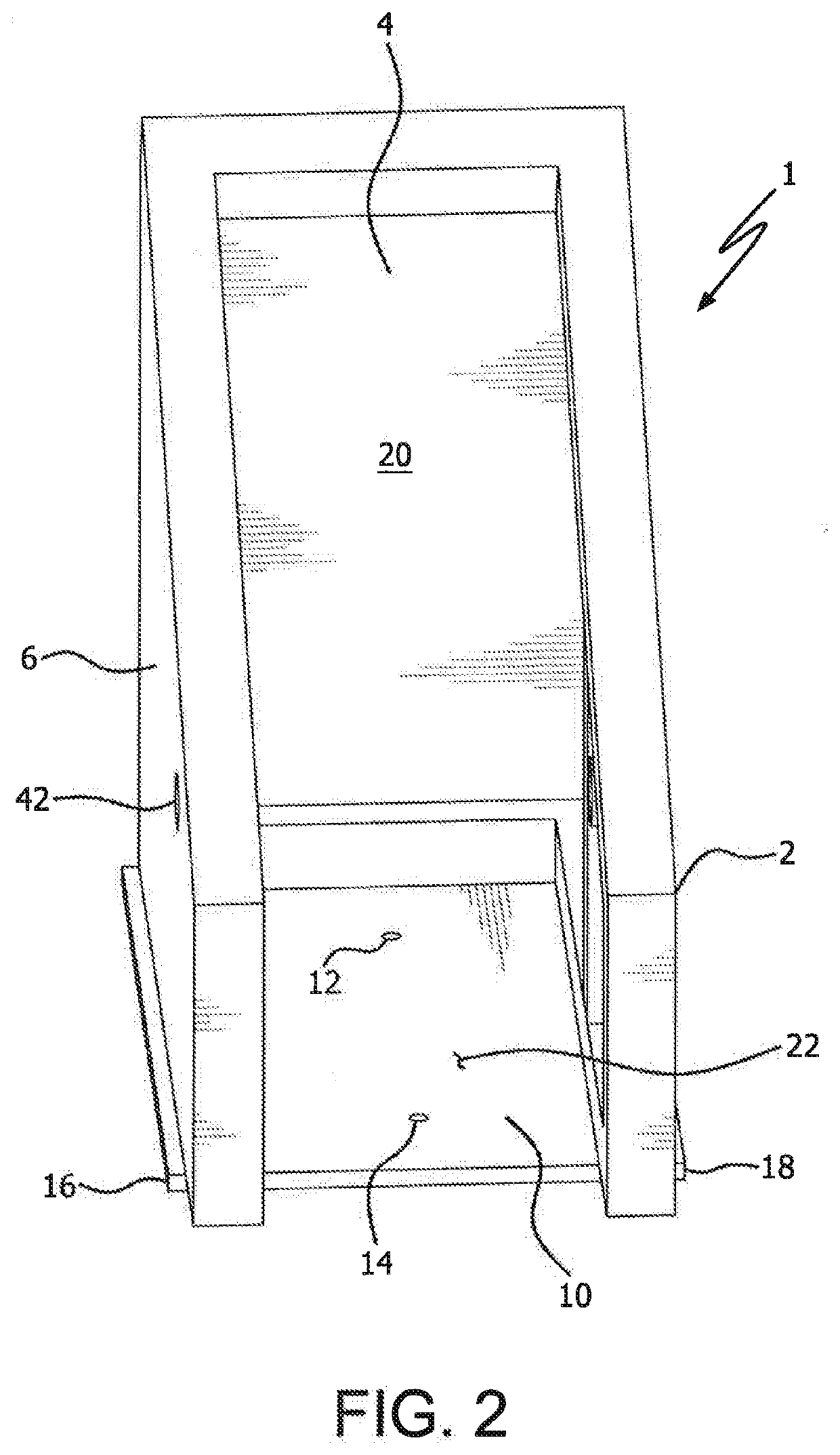
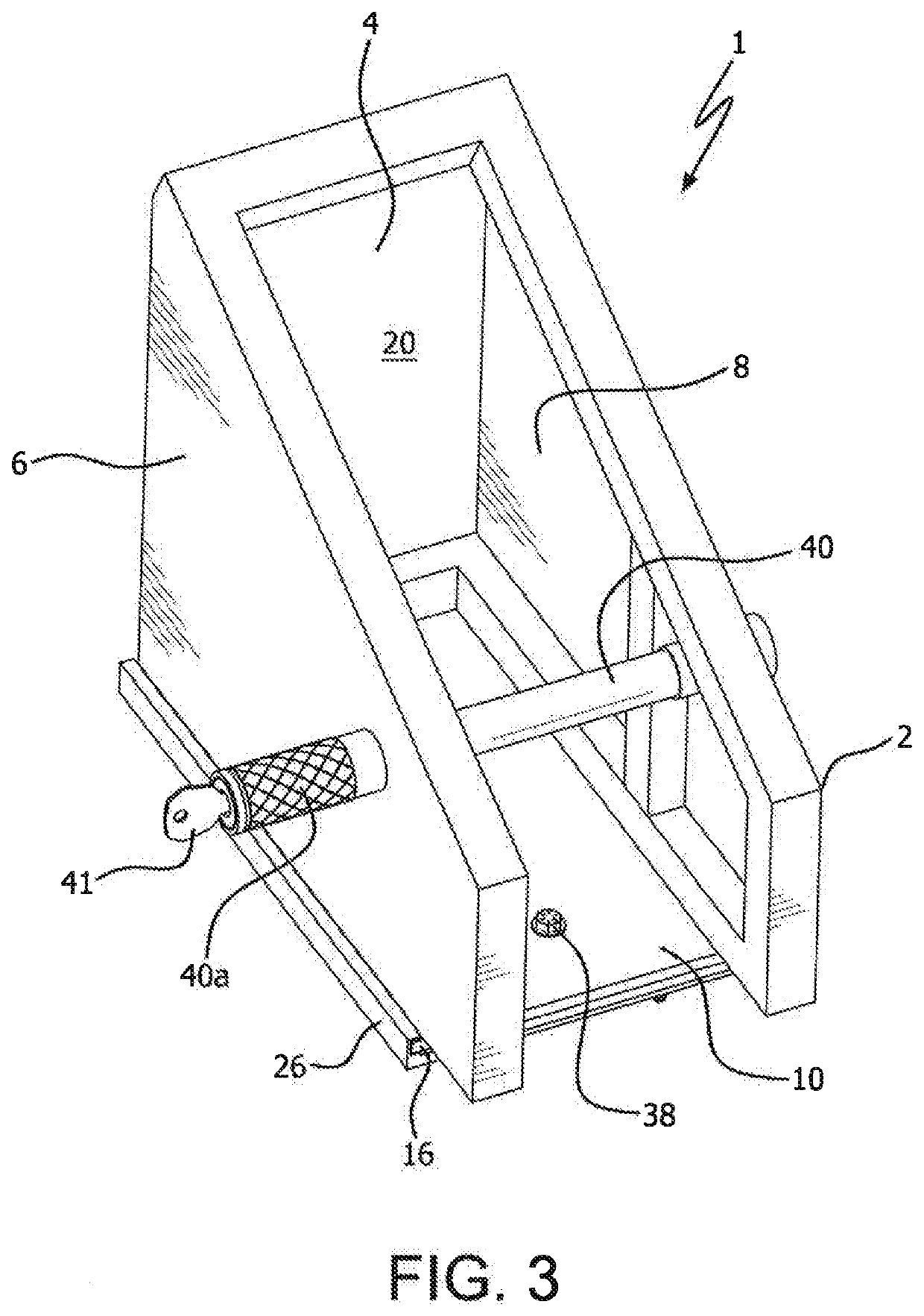
[0011]The motorcycle locking system 1 of the present invention comprises locking housing 2 having back wall 4, sidewalls 6 and 8 extending outwardly from the back wall, and bottom floor 10 located below sidewalls 6 and 8. Holes 12 and 14 extend through the bottom floor 10. Lateral sections 16 and 18 of bottom floor 10 extend outside sidewalls 6 and 8. Slotted space 20 is partially circumscribed by sidewalls 6 and 8, back wall 4, and bottom floor 10, Slotted space 20 has front opening 22.

[0012]Rail members 26 and 28 extend laterally along the length of locking base 24. Bolt receiving nuts 32 and 34 are positioned in holes which extend into locking base 24.

[0013]In the connected position in which the locking system is poised to receive wheel 60 of motorcycle 62, locking housing 2 is located atop locking base 24 and lateral sections 16 and 18 of bottom floor 10 are located within rail members 26 and 28 of the locking base. In this position, holes 12 and 14 through bottom floor 10 are a...


PUM


Abstract

A system for locking the wheel of a motorcycle and hence the motorcycle itself utilizes a locking housing with a back wall, dual sidewalls, and a bottom floor which partially circumscribe a slotted space for receiving the Wheel of a motorcycle. The bottom floor has lateral sections extending outside the sidewalls. A locking base is provided which has rail members extending along the side of the base, the rail members being configured to slidably receive the lateral sections of the bottom floor. Bolts secure the locking housing to the locking base when the system is assembled to receive the front wheel of a motorcycle. An elongated cycle lock is provided to extend through holes in the sidewalls and the motorcycle wheel positioned within the slotted space, to secure the wheel and thus the motorcycle within the locking housing.

Description

FIELD OF THE INVENTION[0001]The present invention relates to securing and locking parked motorcycles to prevent their unauthorized removal and use.BACKGROUND OF THE INVENTION[0002]Motorcycles, and especially current models, are high performance, expensive vehicles. As a result, motorcycle owners are constantly concerned about the safety of their vehicles, including the potential for theft when cycles are parked or otherwise left unattended.[0003]While there have been a number of attempts to provide effective motorcycle locks and locking systems, most have significant drawbacks. For example, many locks are just not strong or hefty enough to keep a thief from easily removing the lock or merely absconding with both the cycle and the lock. Other locks and locking devices have a number of components and thus are quite complex, such that they are not only difficult and cumbersome to operate, but are also expensive to manufacture. There are currently no motorcycle locking systems which are...

Claims


Application Information

Patent Timeline
IPC IPC(8): B62H5/14B62H3/08
CPCB62H3/08B62H2700/005B62H5/145B62H5/148
Inventor ERRICKSON, JR., MICHAEL W.
Owner ERRICKSON JR MICHAEL W
Learn More