Vehicle Leveler with Lighting Safety Features

a technology of safety features and levelers, which is applied in the direction of vehicle components, signalling/lighting devices, loading/unloading, etc., can solve the problems of not being the surface is not highly adjustable, and the prior art levelers are not able to accommodate all types of vehicles, etc., to achieve the effect of minimizing the internal floor slop

Pending Publication Date: 2022-05-26
LEUM ENG INC
View PDF0 Cites 0 Cited by
  • Summary
  • Abstract
  • Description
  • Claims
  • Application Information

AI Technical Summary

Benefits of technology

[0010]It is an object of this invention to provide a vehicle leveler which is highly adjustable and can elevate both the rear and front axles of a vehicle at the same time so as to minimize the slope of the internal floor of the vehicle or trailer.

Problems solved by technology

The majority of vehicle levelers have ramp surfaces which are not highly adjustable.
This is a distinct disadvantage when vehicles are being loaded or unloaded with cargo.
Levelers of the prior art are also not able to accommodate all types of vehicles.
This is yet another disadvantage.

Method used


Image

  • Vehicle Leveler with Lighting Safety Features
  • Vehicle Leveler with Lighting Safety Features
  • Vehicle Leveler with Lighting Safety Features

Examples


Embodiment Construction

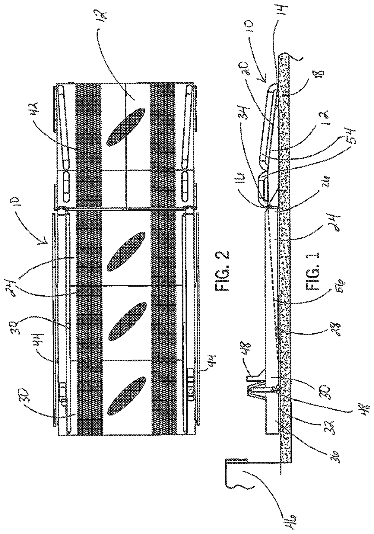
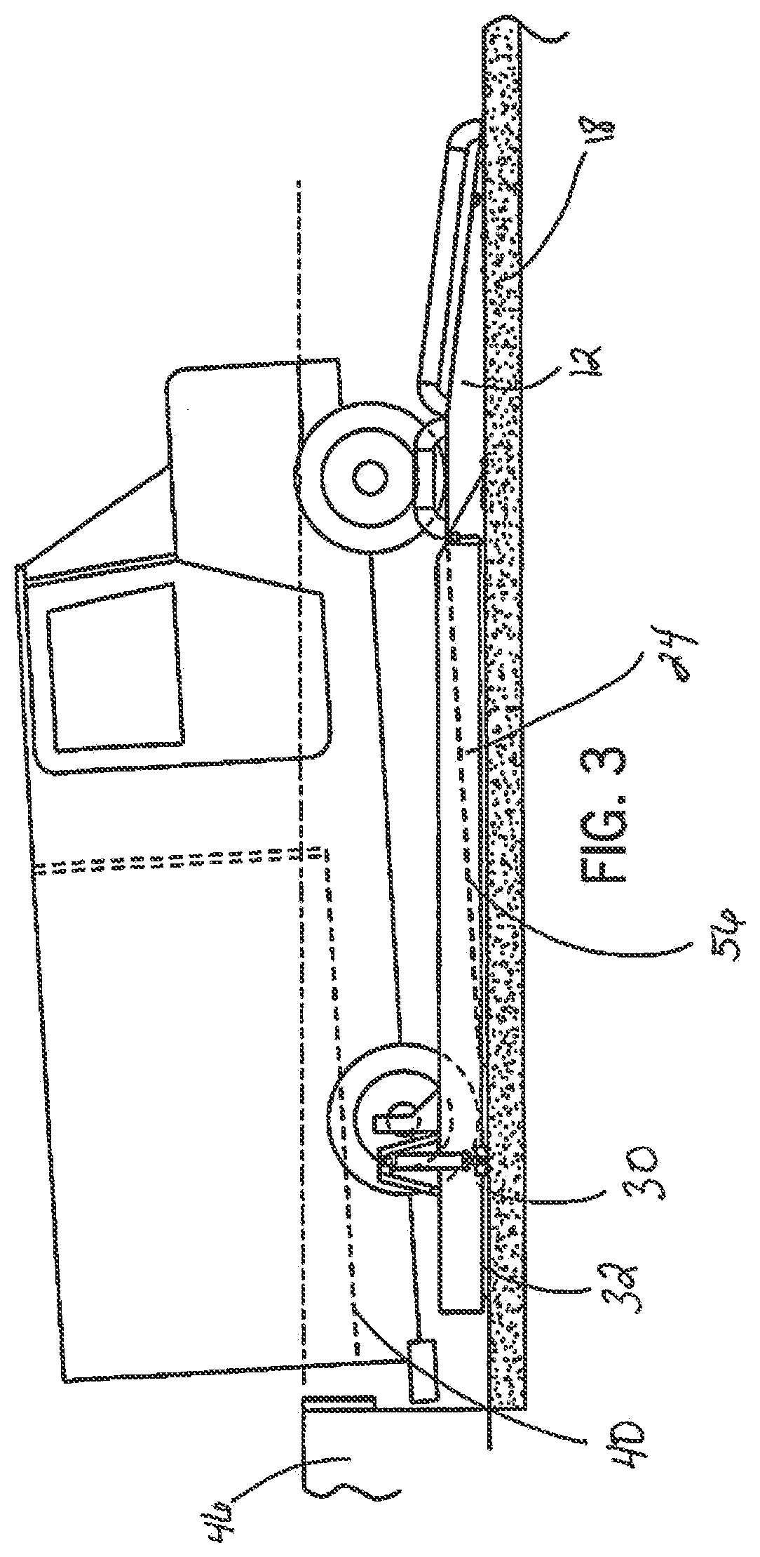
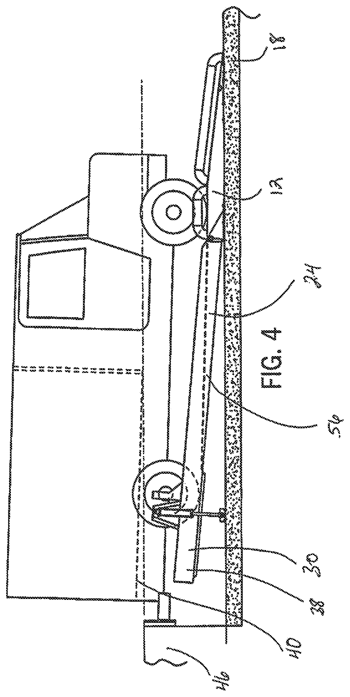
[0050]A preferred embodiment of the present invention is shown in FIGS. 1-24. Vehicle leveler 10, as shown in FIG. 1, includes three primary portions; a first portion 12, a second portion 24 and an extension portion 30 and is designed to be utilized in conjunction with a substantially flat driveway 18 near a loading dock wall 46. Furthermore, leveler 10 can be moved between a lowered position 36, shown in FIGS. 1 and 3 and a raised position 38, shown in FIGS. 4-6.

[0051]First portion 12 has a ramp section 20 which is inclined upwards and a flat section 22 adjacent ramp section 20. First portion 12 includes a leading edge 14 and a trailing edge 16. Trailing edge 16 is disposed further from driveway 18 than leading edge 14. Trailing edge 16 is part of flat section 22. Flat section 22 is disposed about parallel with substantially flat driveway 18.

[0052]FIG. 1 illustrates that second portion 24 has a leading edge 26 and a trailing edge 28. Leading edge 26 of second portion 24 is removabl...


PUM


Abstract

The vehicle leveler includes a first portion which has a leading edge and a trailing edge, the trailing edge is disposed further from the driveway than the leading edge. The embodiment also includes a second portion which has a leading edge and a trailing edge, the leading edge of the second portion is attached to the trailing edge of the first portion and the leading edge of the second portion is disposed further from the driveway than the trailing edge of the second portion. The device has opposing side portions and a walkway. The opposing side portions include at least one or more lights which illuminate the leveler and the walkway.

Description

RELATED APPLICATION[0001]This application is a continuation-in-part of patent application Ser. No. 17 / 550,870, filed on Dec. 14, 2021, which is a continuation-in-part of patent application Ser. No. 17 / 468,882, filed on Sep. 8, 2021, which is a continuation-in-part of patent application Ser. No. 17 / 355,160, filed on Jun. 22, 2021, which is a continuation-in-part of patent application Ser. No. 17 / 340,670, filed on Jun. 7, 2021, which is a continuation-in-part of patent application Ser. No. 17 / 322,889, filed on May 17, 2021, which is a continuation-in-part of patent application Ser. No. 17 / 174,301, filed on Feb. 11, 2021, which is a continuation-in-part of patent application Ser. No. 17 / 026,642, filed on Sep. 21, 2020, which is a continuation-in-part of patent application Ser. No. 16 / 376,910 filed on Apr. 5, 2019, issued on Oct. 27, 2020 as U.S. Pat. No. 10,815,103. Such prior applications are incorporated by reference herein in their entirety.FIELD OF THE INVENTION[0002]This invention...

Claims


Application Information

Patent Timeline
Patent Type & Authority Applications(United States)
IPC IPC(8): B65G69/28B65G69/00B60Q1/30
CPCB65G69/2882B65G69/006B60Q1/307B65G69/005B65G69/2811
Inventor LEUM, GRANTDEMERATH, ERIC
Owner LEUM ENG INC
Why Eureka
Try Eureka