Image forming apparatus

Pending Publication Date: 2022-10-06
CANON KK
View PDF3 Cites 1 Cited by
  • Summary
  • Abstract
  • Description
  • Claims
  • Application Information

AI Technical Summary

Benefits of technology

The present invention provides an image forming apparatus that can adjust the transfer voltage to prevent image density lowering when transferred onto a second side of a recording material. This is achieved by detecting the current outputted from the power source and acquiring information on the density of the image transferred on the recording material. The controller can select the test toner images for setting the transfer voltage and adjust the transfer voltage for the second side of the recording material based on the information on the densities of the test toner images. The technical effect is to improve the image quality and consistency of image formation across the entire recording material.

Problems solved by technology

However, conventionally, there was a case that depending on an image actually transferred on the recording material, proper transfer cannot be made in some instances at a secondary transfer voltage adjusted for transfer for the image on a second side (select) on the basis of the above-described adjusting chart.
For that reason, conventionally, the secondary transfer voltage becomes excessively low, and thus the transfer is not sufficiently carried out, with the result that a density lowering can occur in the image on the second side.

Method used


Image

  • Image forming apparatus
  • Image forming apparatus
  • Image forming apparatus

Examples


first embodiment

[0036]In the following, an image forming apparatus according to a first embodiment will be described with reference to the drawings.

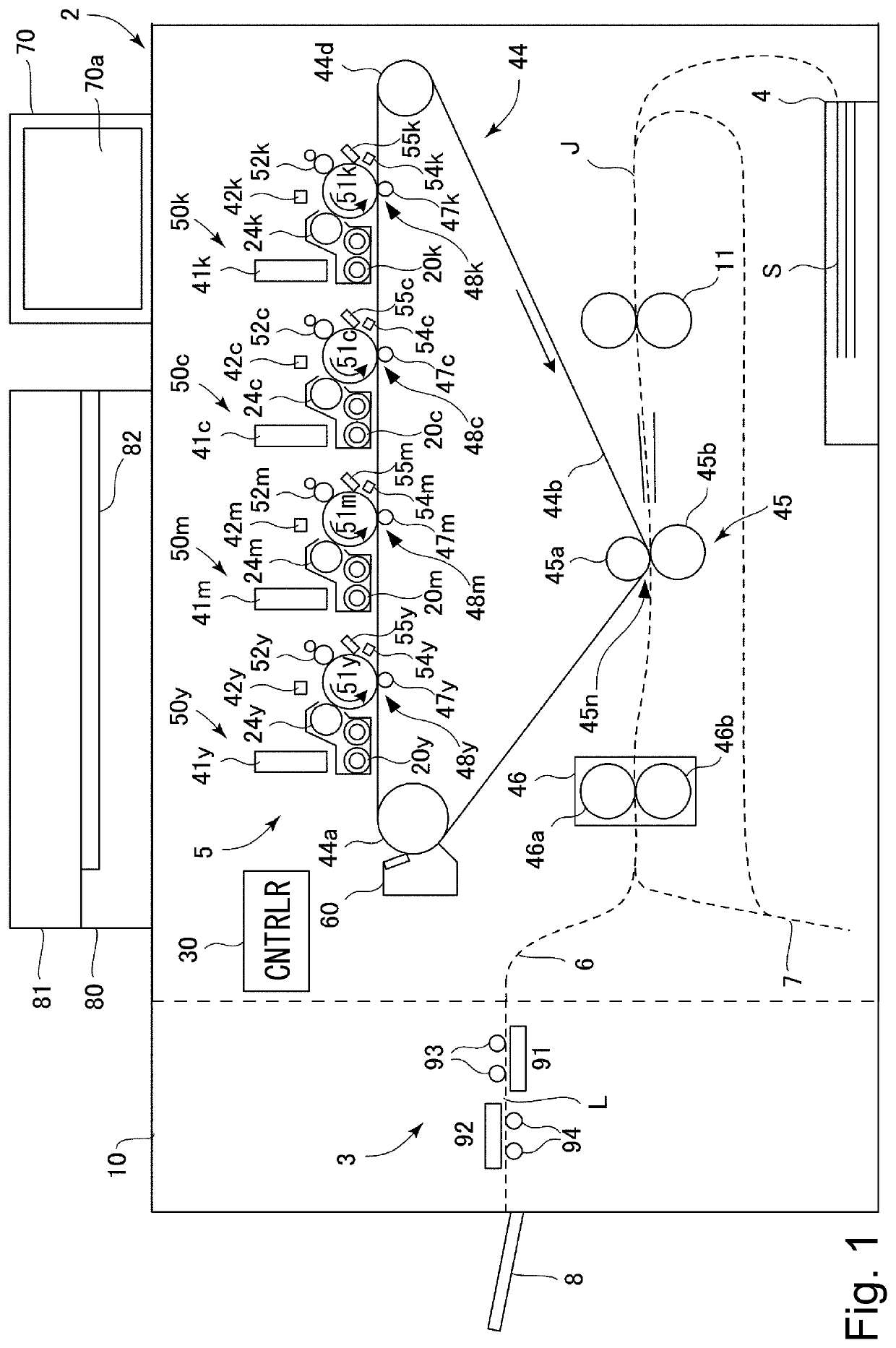
[0037]FIG. 1 is a schematic cross-sectional view of an image forming apparatus 2 of this embodiment. The image forming apparatus 2 of this embodiment is a tandem type full-color printer capable of forming a full-color image by using an electrophotographic type and employing an intermediary transfer type. However, the image forming apparatus 2 of the present invention is not limited to a tandem type image forming apparatus, and may be an image forming apparatus of another type. In addition, the image forming apparatus 2 is not limited to an image forming apparatus capable of forming the full-color image, and may be an image forming apparatus capable of forming only a monochromatic (white / black or single color) image. Further, the image forming apparatus 2 may also be various-purpose image forming apparatuses such as printers, various printing machines, c...

second embodiment

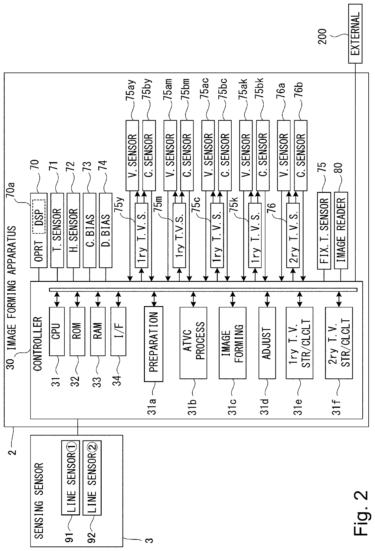
[0149]Next, an image forming apparatus 2A of a second embodiment will be described using FIG. 23. The image forming apparatus 2A is different from the image forming apparatus 2 of the first embodiment described above, and is not provided with the sensing unit 3. For that reason, in the image forming apparatus 2, the recording material S passed through the fixing portion 46 is discharged onto the discharge tray 8 as it is. Other basis constitutions and operations of the image forming apparatus 2A are similar to those in the image forming apparatus 2 of the first embodiment, and therefore, in the image forming apparatus 2A, the constitutions which are the same as the constitutions of the image forming apparatus 2 will be omitted from detailed description by adding the same reference numerals or symbols.

[0150]In this embodiment, patches (test toner images) formed on the adjusting chart is read by the image reading portion 80 in place with the sensing unit 3 (see FIG. 1). That is, the o...


PUM


Abstract

An image forming apparatus includes an image bearing member, an image forming portion, transfer member, a power source, a current detecting portion, an acquiring portion, and a controller capable of executing an operation in an adjustment mode. In the operation in the adjustment mode, the controller selects test toner images for setting a transfer voltage for a second side of a recording material, on the basis of information on densities of the test toner images acquired by the acquiring portion, and then adjusts the transfer voltage for the second side of the recording material on the basis of a current detected by the current detecting portion when the selected test toner images are transferred onto the recording material.

Description

FIELD OF THE INVENTION AND RELATED ART[0001]The present invention relates to an image forming apparatus, such as a printer, a copying machine, a facsimile machine, or a multi-function machine, using an electrophotographic type.[0002]In an image forming apparatus, such as the printer, the copying machine, the facsimile machine, or the multi-function machine, using an electrophotographic type, a toner image formed on an image bearing member such as a photosensitive member or an intermediary transfer member is transferred onto a recording material. The transfer of the toner image from an image bearing member to the recording material is performed by applying a transfer voltage to a transfer member such as a transfer roller which contacts the image bearing member to form a transfer portion (transfer nip). The transfer voltage can be determined based on a transfer portion part voltage corresponding to the electrical resistance of the transfer portion detected during the pre-rotation proc...

Claims


Application Information

Patent Timeline
IPC IPC(8): G03G15/00G06K15/02G03G15/01
CPCG03G15/50G06K15/027G03G15/01G03G15/1675G03G15/5062
Inventor MINATO, YUSUKESUEOKA, TAKENORIKOHNO, TATSUYA
Owner CANON KK
Why Eureka
Try Eureka