
Pneumatic tire

Pending Publication Date: 2022-10-13
TOYO TIRE & RUBBER CO LTD
View PDF0 Cites 0 Cited by
  • Summary
  • Abstract
  • Description
  • Claims
  • Application Information

AI Technical Summary

Benefits of technology

The invention provides a pneumatic tire with good drainage and traction performance. This is achieved through the design of the first and second lateral grooves.

Problems solved by technology

In such pneumatic tire, traction performance is excellent as the main groove has the zigzag shape; however, drainage performance tends to be reduced.

Method used


Image

  • Pneumatic tire
  • Pneumatic tire
  • Pneumatic tire

Examples


Embodiment Construction

[0011]Hereinafter, an embodiment of the present invention will be explained with reference to the drawings. Respective shapes, dimensions and the like in the specification are values in an unloaded normal state where a tire is fitted to a normal rim and is filled with a normal internal pressure unless specially noted. Examples of the normal rim include the “standard rim” in the JATMA standard, the “Design Rim” in the TRA standard, and the “Measuring Rim” in ETRTO standard. Examples of the normal internal pressure include the “maximum air pressure” in the JATMA standard, the “maximum value” described in “TIRE LOAD LIMITS AT VARIOUS COLD INFLATION PRESSURES” in the TRA standard, and “INFLATION PRESSURE” in the ETRTO standard.

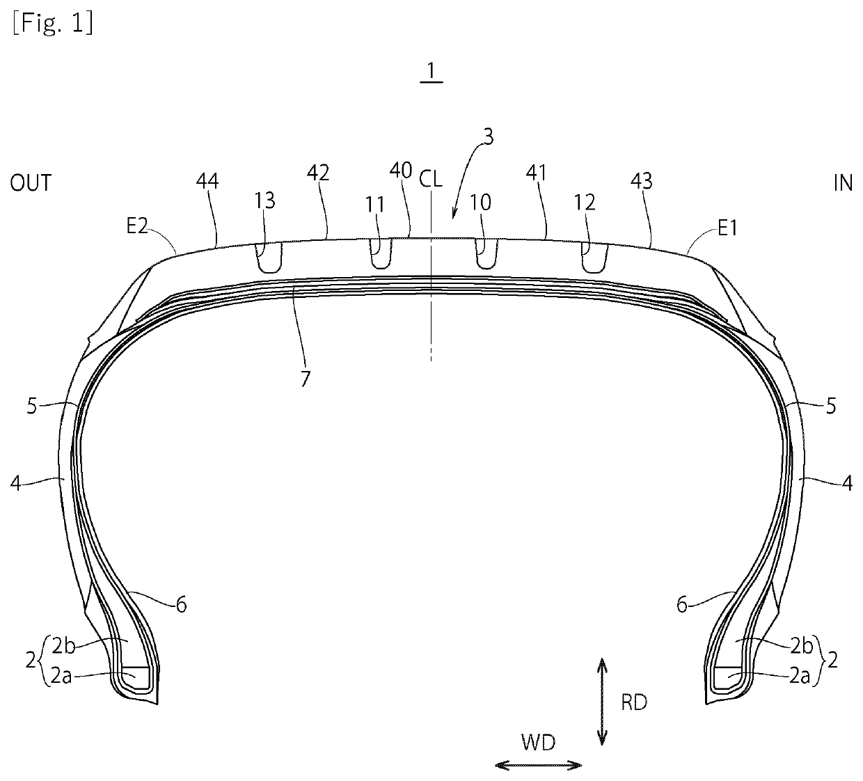
[0012]As shown in FIG. 1, beads 2 are provided on both sides in a tire axial direction of a pneumatic tire 1. Each bead 2 includes a bead core 2a formed of steel wire wound in a circular shape and a rubber bead filler 2b provided on an outer side in a radial direc...


PUM


Abstract

A pneumatic tire includes a circumferential direction groove extending in a zigzag shape with a first groove part and a second groove part being aligned alternately, a first land part and a second land part. A first lateral groove has a first opening that opens to the first groove part, one groove wall of the first lateral groove is connected to a first land part-side second groove wall demarcating the first land part in the second groove part. A second lateral groove has a second opening that opens to the first groove part and longer than the first opening in the tire circumferential direction, one groove wall of the second lateral groove is connected to a second land part-side second groove wall demarcating the second land part in the second groove part, and the second opening is provided on an extension of the first land part-side second groove wall.

Description

BACKGROUND OF THE INVENTION1. Field of the Invention[0001]The present invention relates to a pneumatic tire.2. Description of Related Art[0002]A pneumatic tire including a main groove extending in a zigzag shape in a tire circumferential direction has been hitherto known. In such pneumatic tire, traction performance is excellent as the main groove has the zigzag shape; however, drainage performance tends to be reduced.[0003]A pneumatic tire provided with lateral grooves in a land part demarcated by a zigzag-shaped main groove is known as disclosed in JP-2010-105446. Although the drainage performance can be improved by allowing water to pass inside the lateral grooves in such pneumatic tire, further improvement in drainage performance is required.SUMMARY OF THE INVENTION[0004]The present invention has been made in view of the above circumstances, and an object thereof is to provide a pneumatic tire with good drainage performance and traction performance.[0005]In pneumatic tire includ...

Claims


Application Information

Patent Timeline
IPC IPC(8): B60C11/03B60C11/12
CPCB60C11/0304B60C11/1204B60C11/1236B60C2011/0346B60C2011/1213B60C2011/0374B60C11/0323B60C2011/1245B60C2011/0353B60C2011/0369B60C2011/0365B60C2011/0372B60C2011/0379B60C2011/1209
Inventor SANO, SHINGO
Owner TOYO TIRE & RUBBER CO LTD
Features
  • Generate Ideas
  • Intellectual Property
  • Life Sciences
  • Materials
  • Tech Scout
  • Unparalleled Data Quality
  • Higher Quality Content
  • 60% Fewer Hallucinations
Learn More