
Pneumatic tire

a technology of pneumatic tires and pneumatic wheels, applied in the field of pneumatic tires, can solve the problems of insufficient drainage performance, and achieve the effect of good drainage performance and traction performan

Inactive Publication Date: 2019-06-13
TOYO TIRE & RUBBER CO LTD
View PDF0 Cites 2 Cited by
  • Summary
  • Abstract
  • Description
  • Claims
  • Application Information

AI Technical Summary

Benefits of technology

The patent text describes a design for a pneumatic tire that has good drainage and traction performance. This is achieved by a specific configuration of the center main groove and the first lateral groove. The technical effect of this design is improved tire performance in terms of drainage and traction.

Problems solved by technology

Since the main groove has a zigzag shape, such pneumatic tire is excellent in traction performance, but drainage performance is not sufficient.

Method used


Image

  • Pneumatic tire
  • Pneumatic tire
  • Pneumatic tire

Examples


Embodiment Construction

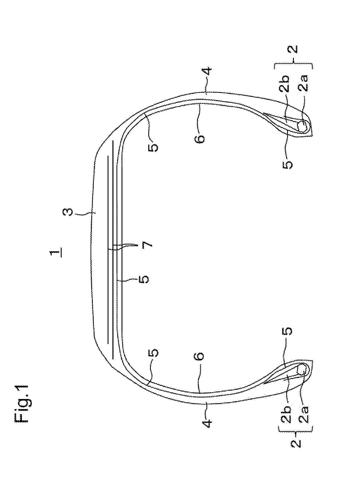
[0015]As illustrated in FIG. 1, a bead portion 2 is provided on both sides in a tire width direction of a pneumatic tire 1. The bead portion 2 is constituted by a bead core 2a made of a steel wire wound in a circular shape and a bead filler 2b made of rubber and provided on a radial outer side of the bead core 2a. A carcass ply 5 is laid across the bead portion 2 on both sides in the tire width direction. The carcass ply 5 is a sheet type member in which a plurality of ply cords arranged in a direction orthogonal to a circumferential direction of the tire are covered with rubber. The carcass ply 5 forms a frame shape of the pneumatic tire 1 between the bead portions 2 on both sides in the tire width direction, and surrounds the bead portions 2 by being folded back from inside to outside in the tire width direction around the bead portions 2. A sheet type inner liner 6 made of rubber having low air permeability is adhered to the inside of the carcass ply 5.

[0016]One or a plurality of...


PUM


Abstract

A pneumatic tire includes a center land portion between two center main grooves, a mediate land portion between a center main groove and a shoulder main groove, and a shoulder land portion between the shoulder main groove and a grounding end (E). Each of the center main grooves extends in a zigzag manner by alternately arranging long first groove portions and short second groove portions that are inclined with respect to a circumferential direction of the tire, respectively. A bulging portion in a tire width direction is formed in the center land portion. Each of the first groove portions of the center main groove is inclined such that a portion to be grounded later heads toward the grounding end (E) side. Each first lateral groove traverses the mediate land portion and the shoulder land portion and forms a notch in the bulging portion in the center land portion.

Description

CROSS-REFERENCE TO RELATED APPLICATIONS[0001]This application is based on Japanese Patent Application No. 2017-238846 (filed on Dec. 13, 2017) and claims priority from Japanese Patent Application No. 2017-238846. The present disclosure incorporates entire contents of Japanese Patent Application No. 2017-238846.TECHNICAL FIELD[0002]The present disclosure relates to a pneumatic tire.BACKGROUND ART[0003]As disclosed in Patent Document 1 or Patent Document 2, a pneumatic tire having a main groove that extends in a zigzag manner in a circumferential direction of a tire is known. Since the main groove has a zigzag shape, such pneumatic tire is excellent in traction performance, but drainage performance is not sufficient.[0004]Further, as disclosed in Patent Document 1 or Patent Document 3, there has been known a pneumatic tire including a center land portion at the center of a tire width direction, a shoulder land portion at both sides in the tire width direction, and a mediate land porti...

Claims


Application Information

Patent Timeline
IPC IPC(8): B60C11/03B60C11/12
CPCB60C11/0309B60C11/0302B60C11/1204B60C2011/0346B60C2011/0358B60C2011/0388B60C2011/1213B60C2200/14B60C11/032B60C2011/0383B60C2200/04B60C2011/1254B60C2011/0381B60C11/1281B60C11/1236B60C2011/1245B60C11/1307B60C2011/133
Inventor YASUNAGA, TOSHIKAZU
Owner TOYO TIRE & RUBBER CO LTD
Features
  • Generate Ideas
  • Intellectual Property
  • Life Sciences
  • Materials
  • Tech Scout
  • Unparalleled Data Quality
  • Higher Quality Content
  • 60% Fewer Hallucinations
Learn More