Overflow dam with flood discharge function for water conservancy project

A technology for water conservancy projects and overflow dams, which is applied in water conservancy projects, sea area projects, coastline protection, etc., can solve the problems of small adjustment effect and the area of ​​the upstream watershed becomes larger, and achieves the effect of improving labor and saving.

Active Publication Date: 2020-12-04
宁夏瑞力建设工程有限公司
View PDF5 Cites 2 Cited by
  • Summary
  • Abstract
  • Description
  • Claims
  • Application Information

AI Technical Summary

Problems solved by technology

The dam body is a reinforced concrete structure. A culvert is arranged on the top of the dam body. Door slots are provided on the inner and outer walls of both sides of the culvert. In the gate slot, the opening and closing handle at the top of the gate can be freely inserted and inserted. However, this device can only have a small adjustment function during the flood discharge, and it still cannot fundamentally solve the problem of the upstream basin area caused by the raised water level. Bigger problem

Method used


Image

  • Overflow dam with flood discharge function for water conservancy project
  • Overflow dam with flood discharge function for water conservancy project
  • Overflow dam with flood discharge function for water conservancy project

Examples


Embodiment 1

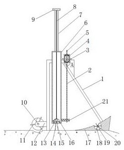
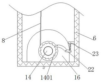
[0029] refer to Figure 1-5 , an overflow dam with a flood discharge function for water conservancy projects, including a dam body 1, the dam body 1 is a prismatic structure with a cavity inside, and a gap is reserved in the middle of the dam body 1, and the opposite side of the gap is opened There are T-shaped chute 15, and between the two T-shaped chute 15 is slidably connected with the same board 6 with a cavity in a flat cuboid structure, and the bottom end of the board 6 is embedded with a wheel box 16 The two ends of the runner box 16 are rotatably connected with the same shaft 14, and the outer wall of the middle part of the shaft 14 is fixed with runners 13 equidistantly distributed, and the outer wall around the shaft 14 is evenly sleeved near both ends. A rope winding wheel is connected, and the outer wall of the rope winding wheel is fixed with a sling 8, the outer wall of the shaft rod 14 is fixed with non-return teeth 1401 near both ends, and the inner wall of the...

Embodiment 2

[0037] refer to figure 1 , an overflow dam with a flood discharge function for water conservancy projects. Compared with Embodiment 1, this embodiment also includes a seesaw 17 arranged at the bottom of the dam body 1 close to the water outlet position, and the curved surface of the seesaw 17 is open. Arc groove 19 is arranged.

[0038] Wherein, the drive shaft 20 is connected with the rotation in the arc groove 19, and the circumferential outer wall of the drive shaft 20 is fixed with runners 2 18 equidistantly distributed, and the two ends of the drive shaft 20 are fixed with a driving pulley, and the wheel groove of the driving pulley The inner sleeve is connected with a conveyor belt.

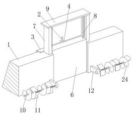
[0039] Wherein, the upstream of the dam body 1 is fixed with a transmission box 12 on both sides close to the bottom gap, and the inside of the transmission box 12 is connected with a transmission rod 10 in rotation near the end, and the peripheral outer wall of the transmission rod 10 is ...


PUM


Abstract

The invention belongs to the technical field of water conservancy projects, and particularly relates to an overflow dam with a flood discharge function for a water conservancy project. When the overflow dam is used and the upstream water level is full during the flood peak period, water blocked by the overflow dam can be completely released only by slowly lifting an inserting plate, when the inserting plate is lifted, the water flow at the bottom impacts on a first rotating wheel, at the moment, a rope winding wheel starts to wind a rope, then a lifting force is provided for the inserting plate, and the problem that the inserting plate is lifted in a more labor-saving mode is solved. According to the scheme, the overflow dam comprises a dam body, wherein the dam body is of a prism-shaped structure with a cavity; a notch is reserved in the middle of the dam body; T-shaped sliding grooves are formed in the opposite sides of the notch; and the same inserting plate with a flat cuboid structure with a cavity is connected between the two T-shaped sliding grooves in a sliding mode. The overflow dam is novel in structure, good in drainage smoothness performance and good in silt dischargingeffect, the high water level can be reduced in time, and the flood discharge capacity and speed are improved.

Description

technical field [0001] The invention relates to the technical field of water conservancy engineering, in particular to an overflow dam with flood discharge function used in water conservancy engineering. Background technique [0002] The overflow dam is actually a low-rolling dam, a low-height water-retaining structure whose main function is to raise the upstream water level and retain mud and sand. The main principle is to raise the water level to a certain position. When the water rises, the excess water can freely overflow to the downstream, and it can also be used as the main part of the water diversion project. After raising the water level, the water will flow along the artificially dug river. Into the artificial river, but the existing rolling dams are all made of concrete stones. Although they are extremely strong, when the water level is raised, the flooded area will be raised at the peak of the flood, and the flood discharge speed will be reduced; in addition to me...

Claims


Application Information

Patent Timeline
Patent Type & Authority Applications(China)
IPC IPC(8): E02B7/26E02B7/36E02B8/04
CPCE02B7/26E02B7/36E02B8/04
Inventor 钱银龙
Owner 宁夏瑞力建设工程有限公司
Why Eureka
Try Eureka