Lever servo unit with changeable elevation angle
A technology of power-assisted mechanism and elevation angle, which is applied in the direction of hoisting device and lifting frame, etc., which can solve the problems that the lift cannot be changed at will, the distance between the platform and the chassis is large, and the hydraulic cylinder cannot be placed completely horizontally, so as to achieve a small distance and an increased elevation angle. Larger, faster lifting effects
- Summary
- Abstract
- Description
- Claims
- Application Information
AI Technical Summary
Problems solved by technology
Method used
Image
Examples
Embodiment 1
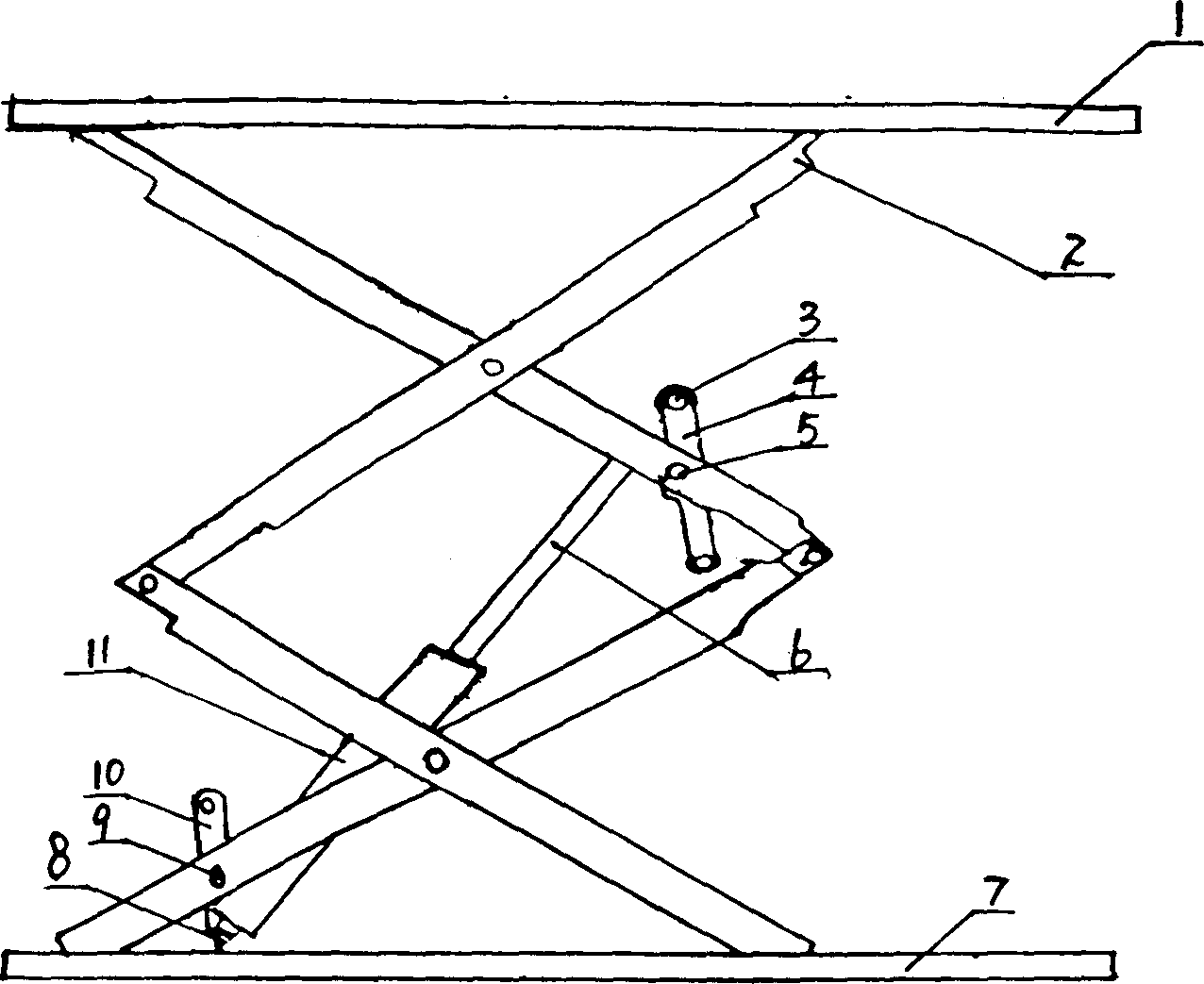
[0013] This embodiment comprises underframe 7, platform 1, support 2, and piston rod 6 and hydraulic cylinder 11, and support 2 is connected between underframe 7 and platform 1, and mutually hinged between support 2, and piston rod 6 and hydraulic cylinder 11 Matching, the connecting block 4 is hinged between the piston rod 6 and the bracket 2, wherein the connecting block 4 and the bracket 2 are hinged through the supporting hinge shaft 5, and the connecting block 4 and the piston rod 6 are hinged through the hinge shaft 3, and the hydraulic cylinder 11 Connect directly to bracket 2.
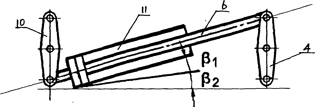
[0014] When this embodiment is folded and placed, due to the existence of the connecting block 4, the hydraulic cylinder 11 can be placed substantially horizontally, and the elevation angle of the centerline of the hydraulic cylinder 11 is increased by β1.
Embodiment 2
[0016] This embodiment comprises underframe 7, platform 1, support 2, and piston rod 6 and hydraulic cylinder 11, and support 2 is connected between underframe 7 and platform 1, and mutually hinged between support 2, and piston rod 6 and hydraulic cylinder 11 Matching, the connecting block 10 is hinged between the hydraulic cylinder 11 and the bracket 2, wherein the connecting block 10 and the bracket 2 are hinged through the supporting hinge shaft 9, the connecting block 10 and the hydraulic cylinder 11 are hinged through the hinge shaft 8, and the piston rod 6 Connect directly to bracket 2.
[0017] When this embodiment is folded and placed, due to the existence of the connecting block 10, the hydraulic cylinder 11 can be placed substantially horizontally, and the elevation angle of the centerline of the hydraulic cylinder 11 is increased by β2.
Embodiment 3
[0019] This embodiment comprises underframe 7, platform 1, support 2, and piston rod 6 and hydraulic cylinder 11, and support 2 is connected between underframe 7 and platform 1, and mutually hinged between support 2, and piston rod 6 and hydraulic cylinder 11 Matching, the connecting block 4 is hinged between the piston rod 6 and the bracket 2, wherein the connecting block 4 and the bracket 2 are hinged through the supporting hinge shaft 5, and the connecting block 4 and the piston rod 6 are hinged through the hinge shaft 3. In the hydraulic cylinder The connecting block 10 is hinged between 11 and the bracket 2, wherein the connecting block 10 and the bracket 2 are hinged through the supporting hinge shaft 9, and the connecting block 10 and the hydraulic cylinder 11 are hinged through the hinge shaft 8.
[0020] When this embodiment is folded and placed, due to the existence of the connecting blocks 4 and 10, the hydraulic cylinder 11 can be placed substantially horizontally, ...
PUM
 Abstract
Description
Claims
Application Information
 - R&D
- Intellectual Property
- Life Sciences
- Materials
- Tech Scout
- Unparalleled Data Quality
- Higher Quality Content
- 60% Fewer Hallucinations
Browse by: Latest US Patents, China's latest patents, Technical Efficacy Thesaurus, Application Domain, Technology Topic, Popular Technical Reports.
© 2025 PatSnap. All rights reserved.Legal|Privacy policy|Modern Slavery Act Transparency Statement|Sitemap|About US| Contact US: help@patsnap.com


