Atomizer with side mist suction channel and integrated atomization assembly
An atomization component and integrated technology, applied in the field of atomizers, can solve the problems of inconvenient automatic production, low production efficiency, poor liquid storage performance, etc., and achieve convenient fully automatic production, improve production efficiency, and good liquid conduction performance. Effect
- Summary
- Abstract
- Description
- Claims
- Application Information
AI Technical Summary
Problems solved by technology
Method used
Image

Examples
Embodiment
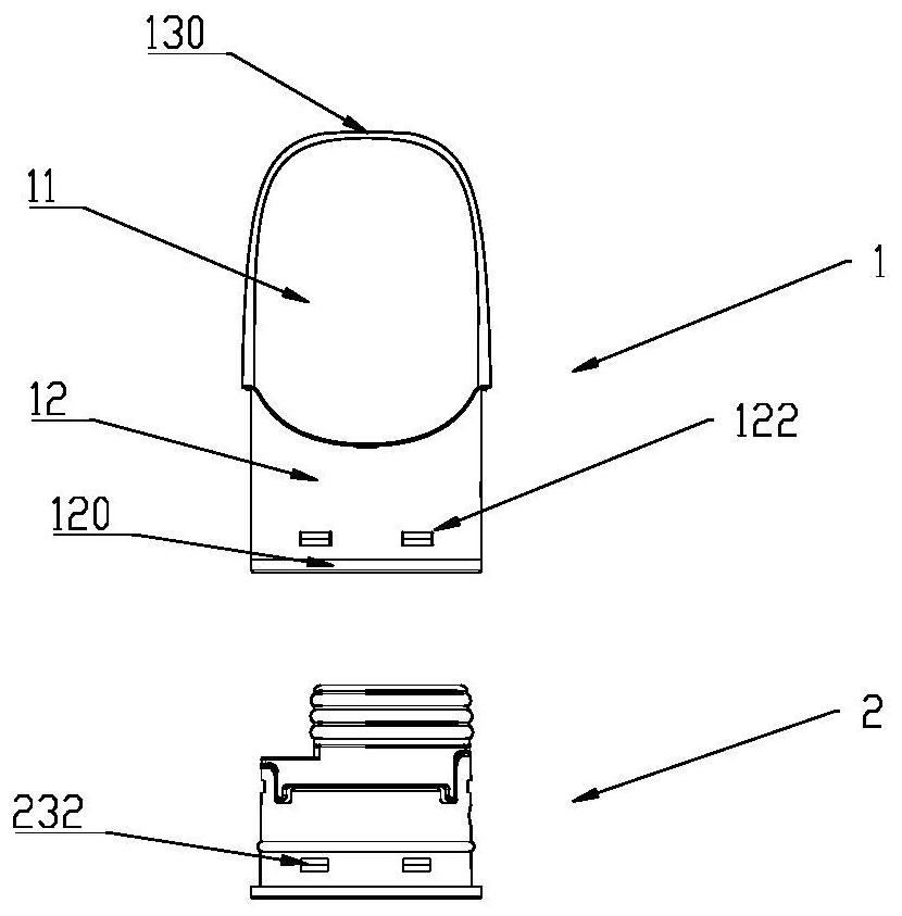
[0044] Such as figure 1 , Figure 11 As shown, an atomizer with a side mist suction channel and an integrated atomization assembly includes an atomization shell 1 and an integrated atomization assembly 2. The atomization shell 1 includes a nozzle end 11 and a connecting end 12. The suction The mouth end 11 is provided with a suction port 110, and the connecting end 12 is provided with an opening 120. The atomizing shell 1 is connected with a battery component (not shown in the figure) through the connecting end 12 to form an electronic atomization device. The opening 120 is installed in the atomizing shell 1 . The one-piece atomization component 2 can be assembled conveniently first, and then put into the atomization shell 1 after the assembly is completed, so that not only the installation quality is reliable, but also the production efficiency can be improved, and it is beneficial to automatic production.
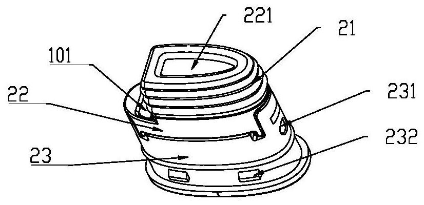
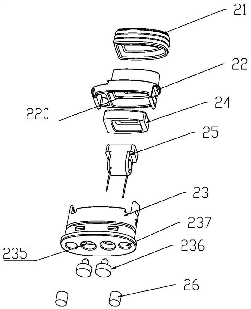
[0045] Such as figure 2 , image 3 , Figure 11 , Figure 12 ...
PUM
 Abstract
Description
Claims
Application Information