
Eureka
For R&D, Eureka makes reading and utilizing patents & technical documents easy.
Eureka AIR
Designed for self-driven R&D workflows. Generate viable solutions, solve complex R&D challenges, empower your innovation with AI.

Eureka Materials
Designed for material experts only. Revolutionize your material R&D, from search, analyze, to developing new materials.

TechResearch
Generate reliable direction feasibility study reports for your R&D in just a few steps.

TechSeek
Discover and master advanced knowledge NOW. Basics, ideas, possibilities, all at once.

TechMind
As an expert in R&D Theories, TechMind can generates customized viable solutions instantly.

TechRisk
Analyze your overall solution with one click, know your potential R&D risks in advance.

TechMonitor
Get weekly tech updates, stay abreast of the latest tech innovations and key insights.
Connector
- Summary
- Abstract
- Description
- Claims
- Application Information
AI Technical Summary
Benefits of technology
Problems solved by technology
Method used
Image

Examples
Embodiment Construction
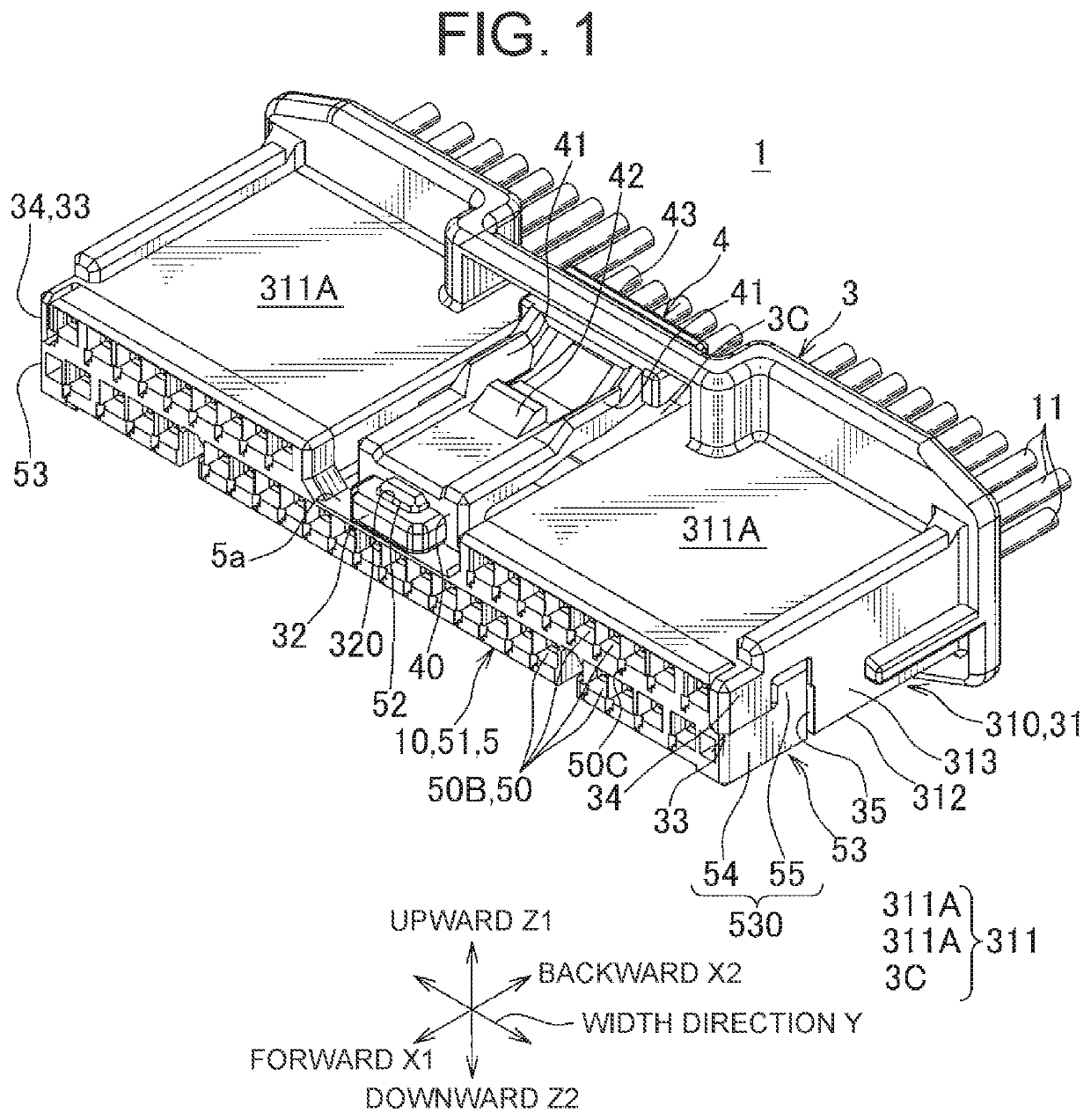
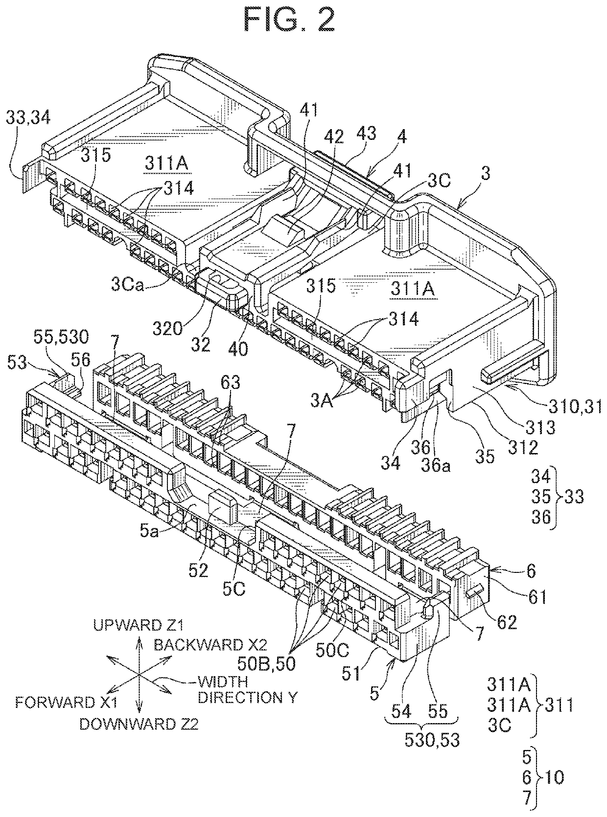
[0019]Hereinafter, an embodiment of the present invention will be described with reference to FIGS. 1 to 10. FIG. 1 shows a perspective view illustrating a connector 1 according to an embodiment of the present invention. FIG. 2 shows a perspective view illustrating a housing 3 and a mounting member 10 forming part of the connector 1.
[0020]As shown in FIGS. 1 and 8, the connector 1 according to the present embodiment includes female terminal metal parts 2 as a terminal according to the claims (hereinafter referred to as “female terminals 2”, see FIG. 8), the housing 3, and a mounting member 10, wherein the female terminals 2 are connected to electric wires 11 (see FIG. 8), the housing 3 includes terminal accommodating chambers 3A (see FIG. 8) for inserting the female terminals 2 therein, and the mounting member 10 is configured to be mounted to the housing 3. The connector 1 forms a terminal section of a wire harness (not shown) to be installed in an automobile. In the present embodi...
PUM
 Abstract
Description
Claims
Application Information
 - R&D Engineer
- R&D Manager
- IP Professional
- Industry Leading Data Capabilities
- Powerful AI technology
- Patent DNA Extraction
Browse by: Latest US Patents, China's latest patents, Technical Efficacy Thesaurus, Application Domain, Technology Topic, Popular Technical Reports.
© 2024 PatSnap. All rights reserved.Legal|Privacy policy|Modern Slavery Act Transparency Statement|Sitemap|About US| Contact US: help@patsnap.com