Beverage container and opening means

a beverage container and opening means technology, applied in the field of beverage containers, can solve the problems of foam head on the liquid, limited liquid flow,

Inactive Publication Date: 2000-01-18
RIGHTENOUR TIM +1
View PDF10 Cites 24 Cited by
  • Summary
  • Abstract
  • Description
  • Claims
  • Application Information

AI Technical Summary

Problems solved by technology

The problem with such a single aperture beverage can is that the flow of liquid is limited by flow friction caused by an inadequate air supp...

Method used


Image

  • Beverage container and opening means
  • Beverage container and opening means
  • Beverage container and opening means

Examples


Embodiment Construction

of the Figures

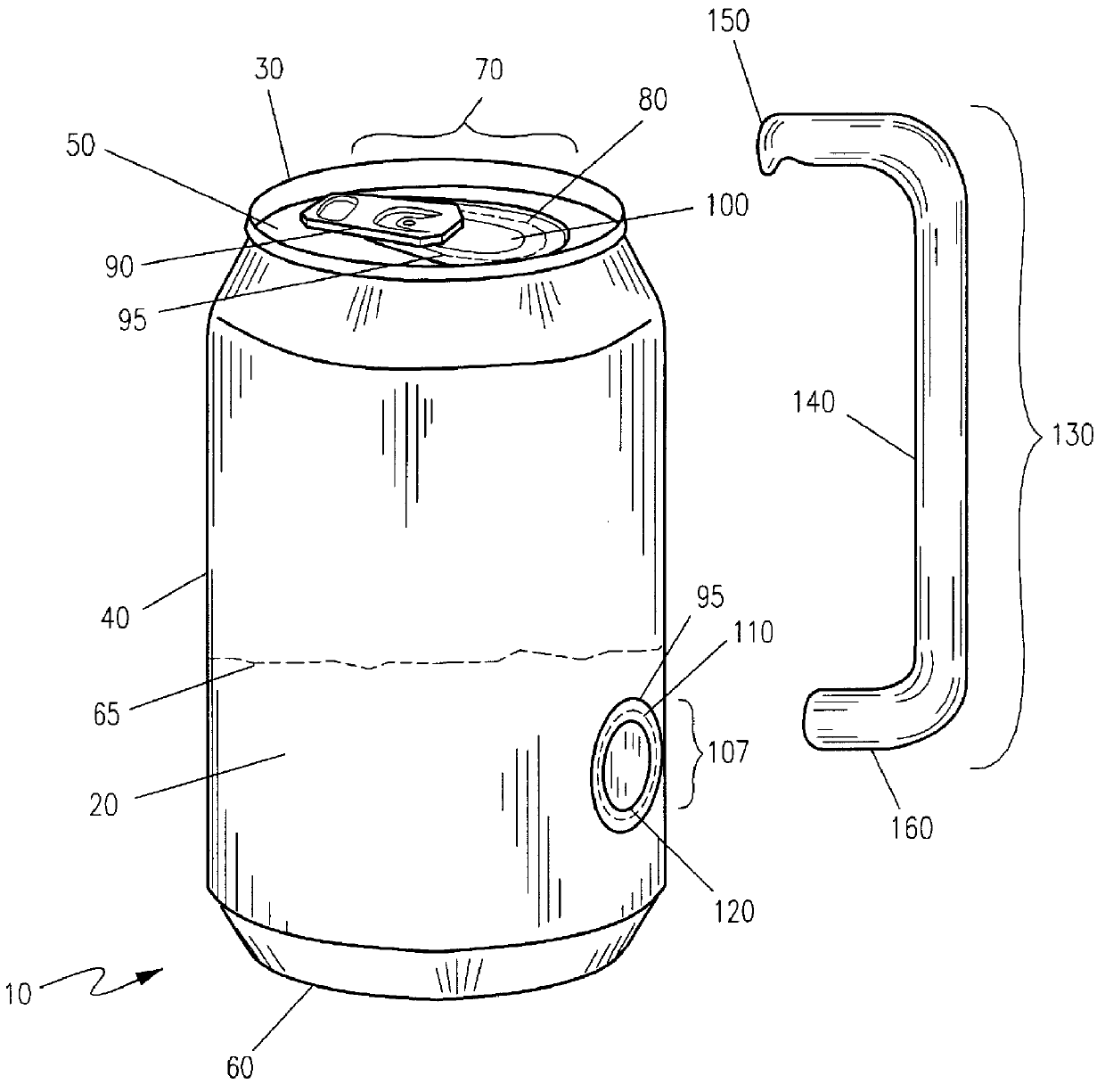
Referring now to FIG. 1, a dual aperture beverage container 10 is shown, according to the present invention, comprising a container 20 of traditional cylindrical configuration, constructed from metal, and used to hold carbonated and malt beverages. The container 20 consists of a container rim 30, container side walls 40, a container top 50 and a container bottom 60, as found in traditional beverage containers 20 of this sort. The container 20 is capable of holding a specified quantity of liquid 65.

Referring now to FIG. 2, located along the container top 50 is a traditional beverage pouring assembly 70, including an elliptical pouring scored portion 80 with a pouring tab 90 attached to the container top 50 near the scoring 95 of the pouring scored portion 80 such that the pouring tab 90 acts as a fulcrum to open the pouring aperture 100.

Referring now to FIG. 3, located on the container side wall 40 is a venting aperture assembly 107. The venting aperture assembly 107 co...


PUM


Abstract

A dual aperture beverage container is disclosed, consisting of a beverage container of traditional cylindrical shape, with a traditional pouring aperture assembly on the top of the container, such as a scored section and a tab. Located along the container side wall is a second scored portion. A venting aperture opener is included which hooks onto the top container rim and opens the venting scored portion to reveal a venting aperture. The venting aperture container can be used to provide additional air to the pouring aperture, or can itself be used as a pouring aperture. Also disclosed is a venting scored portion and venting tab, located on the container bottom, serving the same purpose as the venting aperture located on the container side wall.

Description

1. Field of the InventionThe present invention relates generally to beverage containers and, more particularly, to a dual aperture beverage container.2. Description of the Related ArtSingle opening beverage cans utilize a single large hole for venting the liquid to be dispensed, be it beer or carbonated beverages. The problem with such a single aperture beverage can is that the flow of liquid is limited by flow friction caused by an inadequate air supply, especially when the container is in the pouring position. The usual, small, elliptical openings give a surging or restricted flow, since the outside air which needs to enter the container during the outward flow of beverage competes for the small space provided by the single opening. Also, the release of carbonation is extensive, resulting in a foam head on the liquid.In order to facilitate a more controlled, efficient, even flow rate, a second aperture is desired. This is especially advantageous for the beverages that are carbonat...

Claims


Application Information

Patent Timeline
IPC IPC(8): B65D17/28B65D17/34B65D17/00
CPCB65D17/165B65D2205/04Y10S220/906B65D2517/0005B65D17/4012
Inventor RIGHTENOUR, TIMJORDAN, DAVID
Owner RIGHTENOUR TIM
Why Eureka
Try Eureka