Cooler insert system

a technology of insert system and cooling chamber, which is applied in the direction of cooling chamber, lighting and heating apparatus, support, etc., can solve the problem of difficulty for users to maintain items in an organized fashion in the storage compartmen

Inactive Publication Date: 2000-03-21
OLSTAD TODD +1
View PDF17 Cites 90 Cited by
  • Summary
  • Abstract
  • Description
  • Claims
  • Application Information

AI Technical Summary

Benefits of technology

FIG. 4 is a perspective view showing the cooler insert system of FIG....

Problems solved by technology

Although the storage compartment within these storage articles typically provide an adequate volume for holding the d...

Method used


Image

  • Cooler insert system
  • Cooler insert system
  • Cooler insert system

Examples


Embodiment Construction

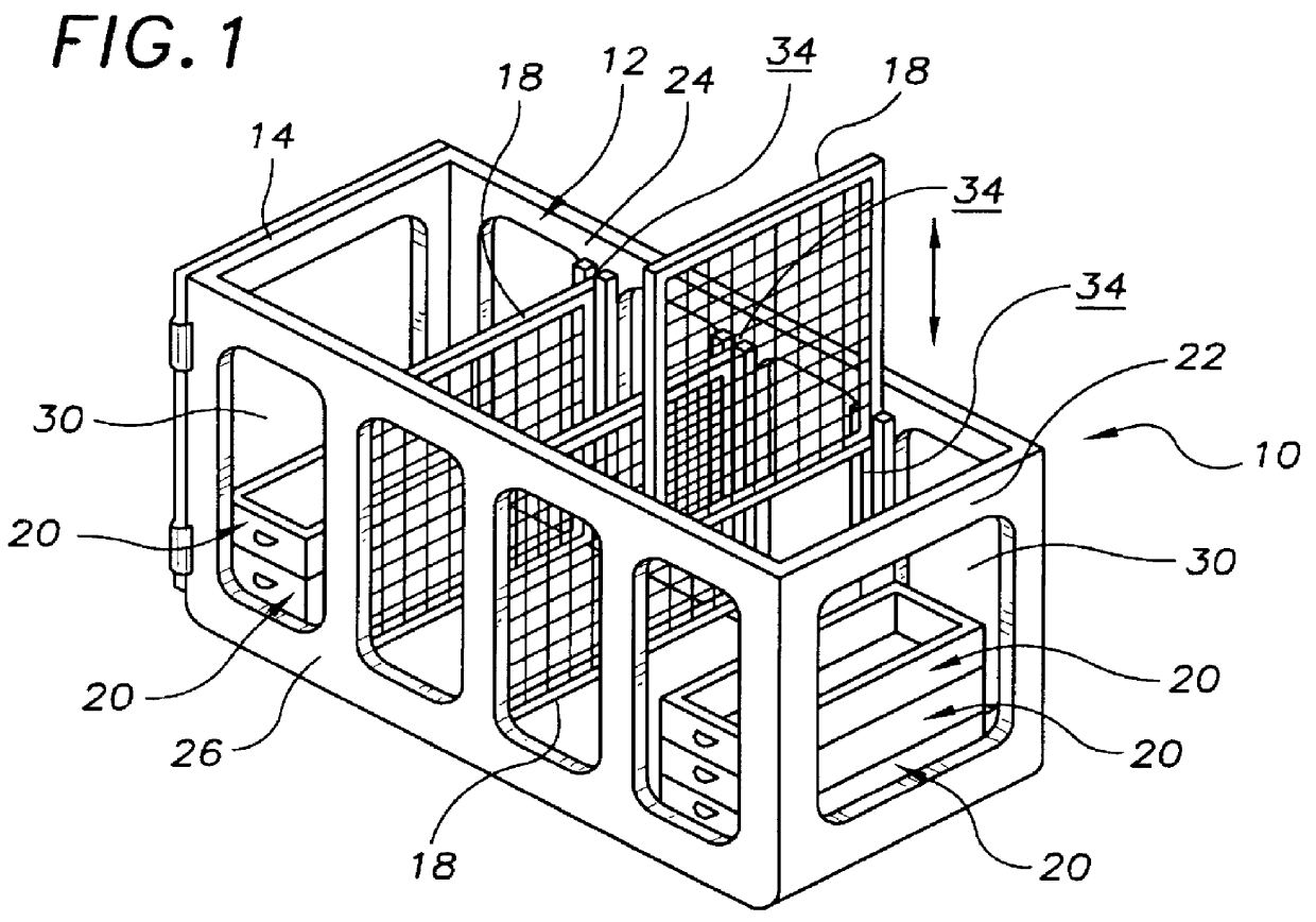
FIG. 1 shows an exemplary embodiment of the cooler insert system of the present invention generally designated by the numeral 10. Cooler insert system 10 includes a molded plastic, open sided, main frame structure, generally designated 12; a molded plastic, snap fit, hinged frame panel 14; three molded plastic, divider screens 18; and five stackable trays, generally designated 20. Main frame structure 12 includes an end wall 22 and two opposed side walls 24,26. End wall 22 and opposed side walls 24,26 each have at least one opening 30 formed therethrough for allowing circulation of ice and cold water in use.

Opposed side walls 22,24 have three pairs of divider screen guide channels 34 (remaining guide channels 34 shown in FIG. 3) within which the side edges of divider screens 18 are inserted to divide the open top box, formed when snap fit, hinged frame panel snap 14 is snap fit to main frame structure 12, into user sized insert compartments.

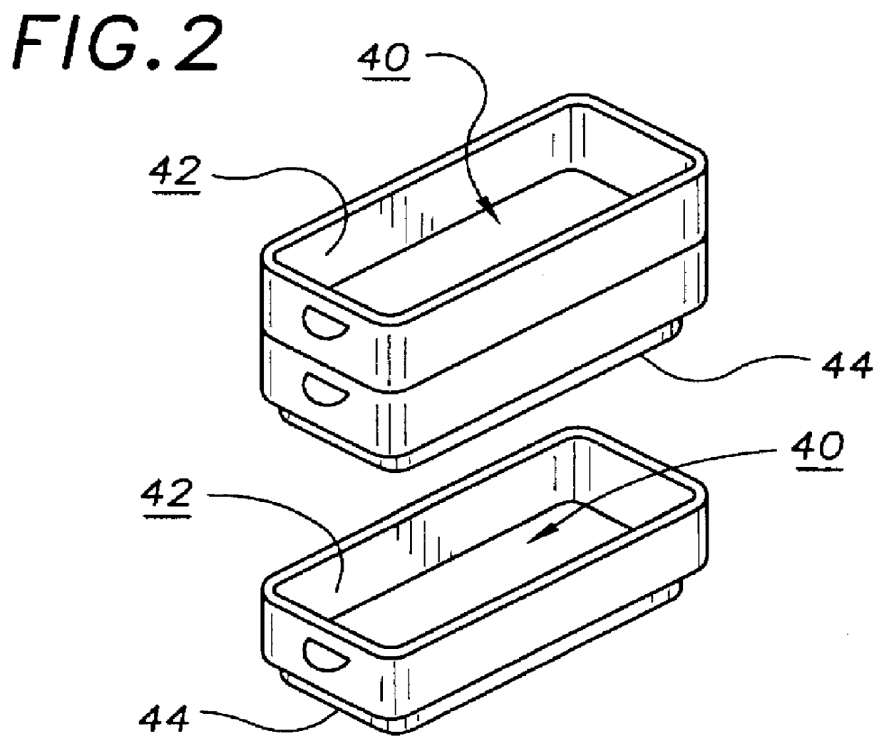
With reference to FIG. 2, stackable trays ...


PUM


Abstract

A cooler insert system that includes an open-sided, main frame structure including an end wall and two opposed side walls, the end wall and the two opposed side walls each having an opening formed therethrough, the two opposed side walls having three pairs of divider screen guide channels; a snap fit, hinged frame panel that is simultaneously snap fittable to an end of each of the two opposed sidewalls of the frame structure to form an open topped box with the main frame structure; three divider screens, each divider screen being insertable into one pair of the three pairs of divider screen guide channels of the main frame structure to divide the interior of the main frame structure into compartments; and a number of stackable trays that are positionable within a compartment formed by one of the divider screens, each stackable tray having a holding cavity defined therein that is accessible through an access opening and a lower registration protrusion extending from the bottom thereof; the registration protrusion being sized and shaped to sealing fit into the access opening of a holding cavity of another tray member and to seal the access opening into the holding cavity.

Description

The present invention relates to accessories for coolers, ice chests and the like and more particularly to a cooler insert system that is insertable into the storage compartment of a cooler, ice chest or the like for organizing items; the cooler insert system including a main, open-sided, frame structure including an end wall and two opposed side walls, the end wall and the two opposed side walls each having an opening formed therethrough, the two opposed side walls having three pairs of divider screen guide channels; a snap fit, hinged frame panel that is simultaneously snap fittable to an end of each of the two opposed sidewalls of the frame structure to form an open topped box; three divider screens, each divider screen being insertable into one pair of the three pairs of divider screen guide channels of the main frame structure to divide the interior of the main frame structure into compartments; and a number of stackable trays that are positionable within a compartment formed b...

Claims


Application Information

Patent Timeline
IPC IPC(8): A45C11/20F25D23/06F25D3/06F25D3/00F25D25/00
CPCA45C11/20F25D23/069F25D3/06F25D25/005F25D2303/081F25D2331/804
Inventor OLSTAD, TODDOLSTAD, MARVEL
Owner OLSTAD TODD
Why Eureka
Try Eureka