Variable speed passenger conveyor and method of operation

a conveyor and variable speed technology, applied in the direction of electric motor speed/torque regulation, transportation and packaging, sustainable buildings, etc., can solve the problems of increasing the complexity of the control system, increasing the risk of overload, and generating peak loads during the operation, so as to improve the reliability of the drive and reduce the size of the converter

Inactive Publication Date: 2000-04-11
OTIS ELEVATOR CO +1
View PDF19 Cites 33 Cited by
  • Summary
  • Abstract
  • Description
  • Claims
  • Application Information

AI Technical Summary

Benefits of technology

As a result of only using the frequency converter for the transitions in speed and the stand-by speed only, rather than to maintain the operation at the nominal speed, the size of the converter may be minimized. In addition, during the operation of the conveyor in the down direction, energy may be regenerated directly to the power source line without the need for additional equipment, such as an energy regeneration system. Further, having available both the frequency converter operation and the line power operation improves the reliability of the drive. In the event of a failure of the frequency converter, the conveyor may be operated in a continuous mode at the nominal speed by the line power until the frequency converter is repaired or replaced.

Problems solved by technology

In modem conveyors, the control systems have become increasingly complex in an effort to improve efficiency and reduce wear and cost of operation.
A drawback to this system, however, is the generation of peak loads during the frequent switching on and off of the conveyor.
While this solution may provide some benefits, even when operated at a reduced speed wear of the escalator components still occurs and energy is wasted during no-load conditions.

Method used


Image

  • Variable speed passenger conveyor and method of operation
  • Variable speed passenger conveyor and method of operation
  • Variable speed passenger conveyor and method of operation

Examples


Embodiment Construction

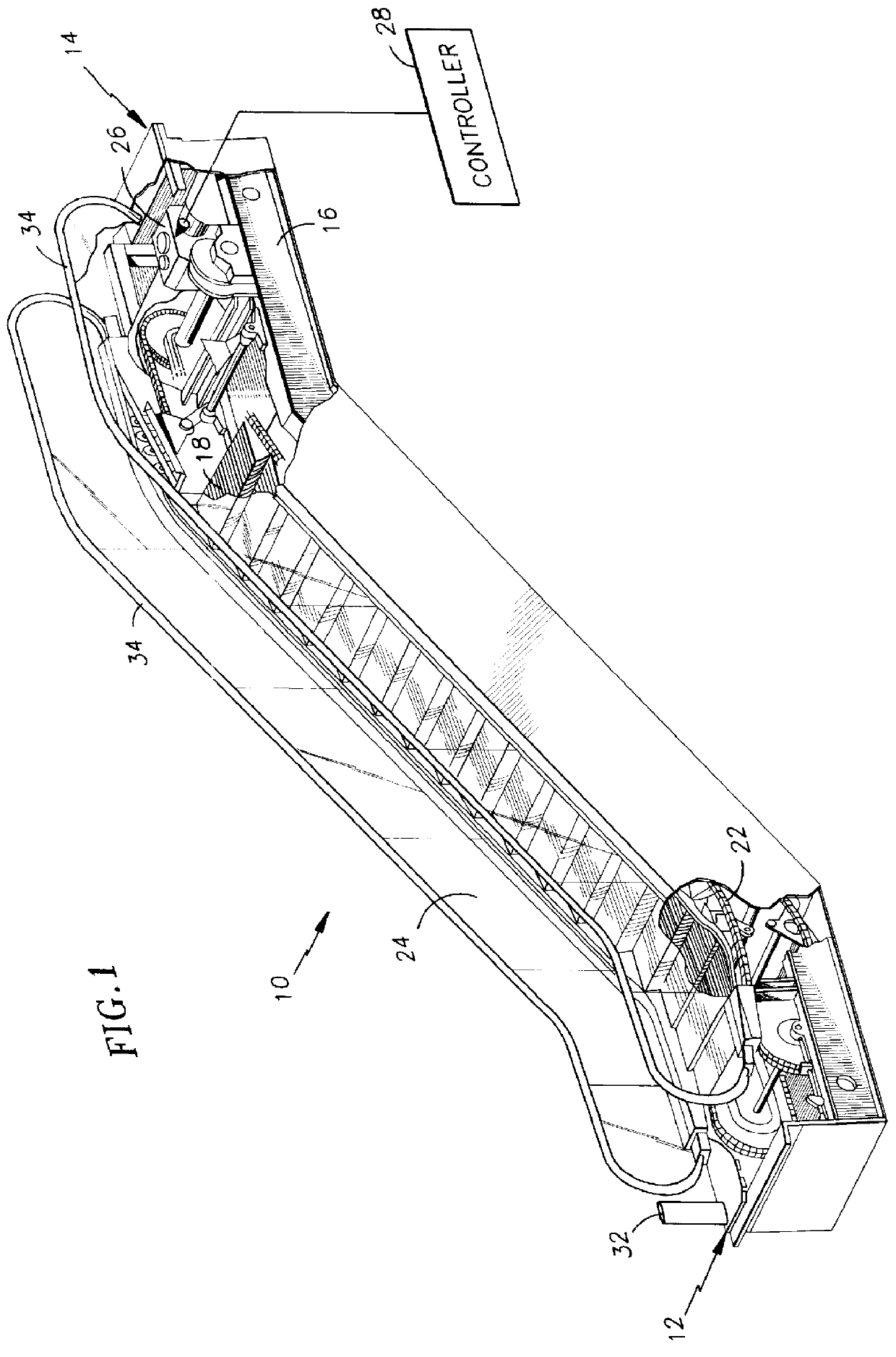
An escalator, as shown in FIG. 1, is used herein as a representative passenger conveyor to illustrate the invention. It will become apparent that the invention is also applicable to other types of passenger conveyors, such as moving walks.

The escalator 10 includes a first landing 12, a second landing 14, a truss 16, a plurality of sequentially connected treadplates 18, a step chain 22 for driving the treadplates 18, a pair of balustrades 24 extending along both sides of the treadplates 18, a drive machine 26 operatively connected to the step chain 22, a controller 28 engaged with the drive machine 26, and a passenger sensor 32. The treadplates define the platforms for carrying passengers between the first and second landings. Each of the balustrades 24 include a moving handrail 34 that is driven at the same speed as the treadplates 18.

The controller 28 determines the power input to the drive machine 26 and thereby controls the speed of the drive machine 26, which in turn controls th...


PUM


Abstract

A control system for a passenger conveyor includes a ready-to-operate mode, a standby speed and a nominal speed. A method to operate the passenger conveyor includes the steps of: transitioning the conveyor from ready-to-operate mode to nominal speed using a frequency converter; switching from frequency converter to line power at nominal speed; switching back to frequency converter if no passengers are present and transitioning from nominal to standby speed; and transitioning from standby speed to ready-to-operate mode if a predetermined amount of time passes without a passenger entering the conveyor.

Description

TECHNICAL FIELDThe present invention relates to passenger conveyors, and more particularly to control systems for such conveyors.BACKGROUND OF THE INVENTIONA typical passenger conveyor, such as an escalator or moving walk, includes a truss, a plurality of sequentially connected treadplates traveling through a closed loop path within the truss, and a machine for driving the treadplates. A control system is used to control the operation of the conveyor for such parameters as speed and direction. Such conveyors are a very efficient means to move large numbers of passengers between floors or locations.In modem conveyors, the control systems have become increasingly complex in an effort to improve efficiency and reduce wear and cost of operation. One such control system incorporates a sensor to detect passengers entering the conveyor. Upon detection of a passenger, the conveyor is switched on and the treadplates begin moving. After the passenger exits the conveyor, the conveyor is switch...

Claims


Application Information

Patent Timeline
Patent Type & Authority Patents(United States)
IPC IPC(8): B66B25/00
CPCB66B25/00Y02B50/225Y02B50/00
Inventor MARKUS, RICHARDSTOXEN, OLIVERTHALER, DIETMAR
Owner OTIS ELEVATOR CO
Why Eureka
Try Eureka