Device for connecting a displaceable element to a guide device

Inactive Publication Date: 2000-04-25
HAWA AG
View PDF10 Cites 86 Cited by
  • Summary
  • Abstract
  • Description
  • Claims
  • Application Information

AI Technical Summary

Problems solved by technology

Moreover, the protrusion of fasteners is also undesirable for aesthetic reasons or for safety reasons.

Method used


Image

  • Device for connecting a displaceable element to a guide device
  • Device for connecting a displaceable element to a guide device
  • Device for connecting a displaceable element to a guide device

Examples


Embodiment Construction

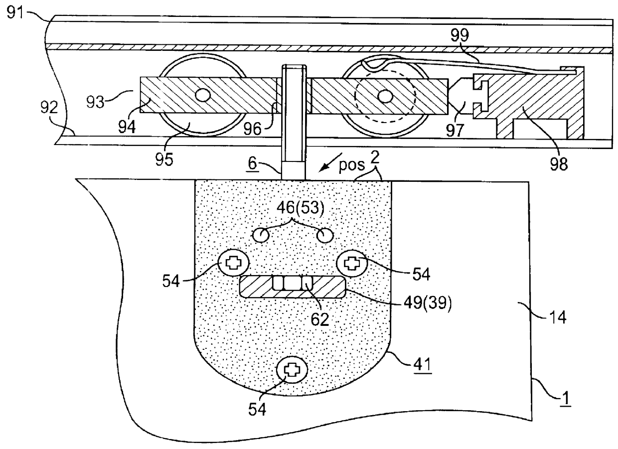
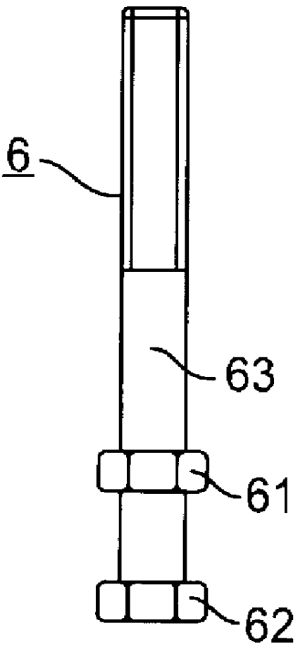
FIG. 1 shows a device 2 in accordance with the invention that is joined on one side with a glass element 1 and on the other side, via a connecting bolt 6 with a carriage 93 that is guided in a track 91 and that has a carriage body 94 and two wheels 95 that roll along a running surface 92 of the guide track 91. The connecting bolt 6, through which the distance between the glass element 1 and the guide track 91 may be adjusted, is screwed into a thread 96 provided in the carriage body 94. Also provided in the guide track 91 is a bracket 98 with a bumper 97 that serves the cushioning of the carriage. The bracket 98 carries a spring element 99 that holds the carriage 93 in place as soon as this touches with the bumper 97.

Such carriages and associated tracks are known in the art, for example, from EP 0 733 766 A2 or EP 0 305 634 A1. However, implementation of the solution in accordance with the invention is also possible with other carriages known in the art.

In an advantageous embodiment...


PUM


Abstract

PCT No. PCT/CH98/00274 Sec. 371 Date Feb. 23, 1999 Sec. 102(e) Date Feb. 23, 1999 PCT Filed Jun. 23, 1998 PCT Pub. No. WO98/59140 PCT Pub. Date Dec. 30, 1998Device for connecting a displaceable element, especially a glass, metal or wooden panel to a guiding device that is guided in a rail. The device includes first and second fixing members which each contain outer panels and fitting, elements which can be interconnected by an axle. The fitting elements are inserted into a cutout section on the edge of the displaceable element and interconnected. The fitting elements encompass a connection screw which can be connected to the guide device, the connection screw having a screw shaft with a screw head, a locking element and a thread. The fitting element of the first fixing member has a channel for receiving the screw shaft, the channel having channel walls, a trough for receiving the screw head and a cavity for receiving the securing element. The locking element can be stopped by a stop screw. The fitting element of the second fixing member has a recess for receiving the channel walls and an opening through which the screw head can be accessed. The assembled device can be adjusted by loosening the stop screws by a few turns and turning the connection screw until the displaceable element is set at the desired height. The stop screws are then re-tightened. The locking element is part of the connection screw and is encompassed in the device so that the top edge of the displaceable element can be drawn practically up to the rail.

Description

1. Field of the InventionThe present invention concerns a device for joining a sliding element, such as a glass, metal or wooden panel, with a guide device.DISCUSSION OF BACKGROUND INFORMATIONTo close room openings, sliding doors are often used that are suspended from a carriage that is guided on a track. For this purpose, a device is provided that is attached to the sliding door and connected to the carriage via a connecting bolt. From EP 0 733 766 A2, such a device is known that consists of a mounting piece that is screwed to a sliding wooden door and is intended for the accommodation of a connecting bolt that is screwed into the carriage. The head of the connecting bolt, which is mounted to rotate in the opened mounting piece, can be fixed in place by means of a safety cover, by which the mounting piece is closed. By opening the safety cover, the connecting bolt of the mounting piece (and the sliding door) can be loosened or tightened, so that the height of the sliding door can b...

Claims


Application Information

Patent Timeline
IPC IPC(8): E05D15/06E05F5/00
CPCE05D15/063Y10T16/353E05Y2201/218E05Y2201/22E05Y2201/638E05Y2201/64E05Y2201/688E05Y2201/702E05Y2600/20E05Y2800/672E05Y2201/48Y10T16/3543Y10T16/35Y10T16/3816E05F5/003E05Y2900/00E05D15/06
Inventor HAAB, KARLHAAB, OTTO
Owner HAWA AG
Why Eureka
Try Eureka