Dual-position assist and guard rail for beds

a guard rail and assist technology, applied in the field of side guards or guard rails for beds, can solve the problems of difficult patient treatment, expensive hinges, and inability to maneuver patients,

Inactive Publication Date: 2000-05-09
CARROLL HEALTHCARE
View PDF12 Cites 156 Cited by
  • Summary
  • Abstract
  • Description
  • Claims
  • Application Information

AI Technical Summary

Benefits of technology

The present invention, in one embodiment, provides an improvement in a bed having a side rail structure, and at least one dual-position rail assembly which is mounted on such side rail structure, the improvement including: a rotatable structure which is mounted upon the dual-position rail assembly, to enable the dual-position rail assembly to move between two positively-stopped and automatically locked positions, a first of the positively-stopped and automatically locked positions disposing the dual-position rail assembly in an assist, v

Problems solved by technology

While these devices seemed to serve the purpose for which they were intended, they brought about the disadvantage that they made it difficult to treat the patient and also caused considerable difficulty during the changing of the sheets or blankets on the bed.
The other typical type comprised a similar side rail structure which had a complicated and expensive hinged mechanism to allow the side rail to be lowered to the floor.
This was thought to be more convenient for the aide, but it was impossible for the patient to manoeuvre if the patient was in the bed.
First, in several types of such devices of the prior art, the bed rail mechanism was not movable through a vertical plane that was parallel to the edge of the bed.
Secondly, most of the known prior art devices are not equipped to withstand force applied horizontally thereof.
More specifically, it has been found that most prior art devices having retractable features provided adequate support against accidental pivoting through the intended plane of movement, there had, in the past, been no adequate provision for withstanding force applied normal to the direction of the intended movement.
While many types of operating mechanisms have been previously devised for movable bed guards, such prior bed guards have been susceptible to pinching or otherwise inj

Method used


Image

  • Dual-position assist and guard rail for beds
  • Dual-position assist and guard rail for beds
  • Dual-position assist and guard rail for beds

Examples


Embodiment Construction

(a) Description of FIGS. 1 & 2

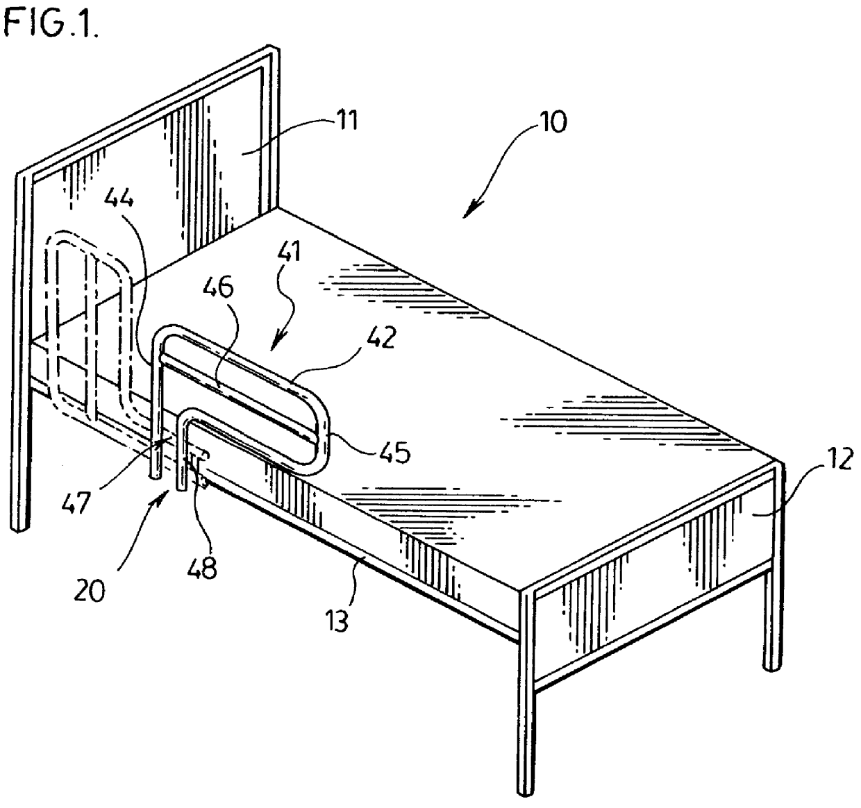
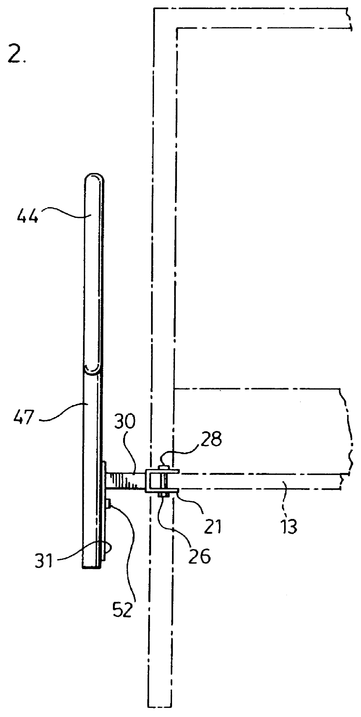
One preferred embodiment of this invention is on a hospital bed. The hospital bed 10 as seen in FIGS. 1 and 2, includes a headboard 11, a footboard 12 and a pair of side rails, (only one 13 being seen), extending therebetween on both sides of the bed. The rail structure 20 is secured to the side rail 13 in a manner which is more clearly seen in FIGS. 2, 3 and 6.

(b) Description of FIG. 3 and FIG. 4

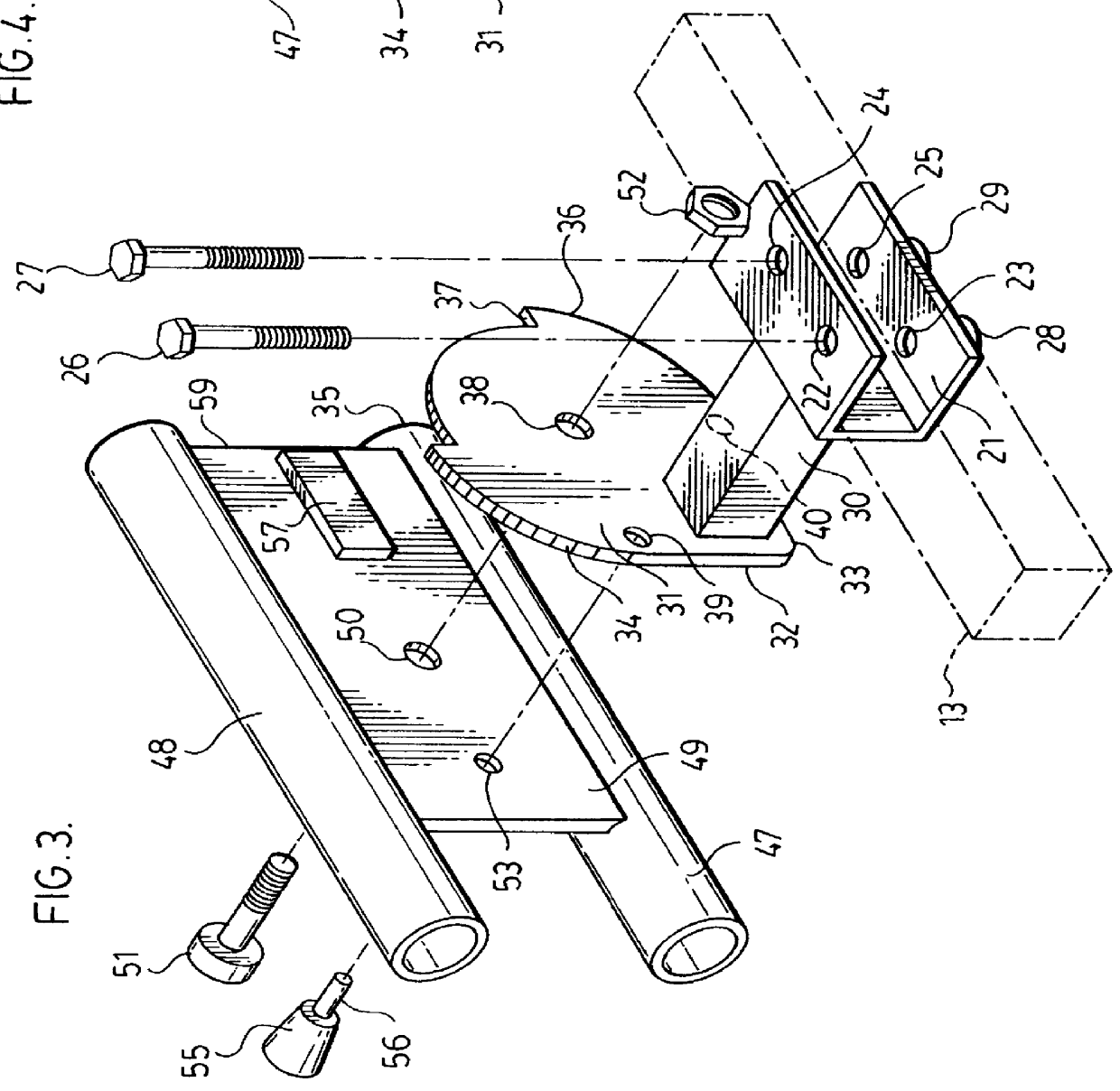
Turning now to FIG. 3 and FIG. 4, the rail structure includes a U-shaped channel bracket 21 which is provided with aligned apertures 22,23 and 24,25, through which bolts 26,27, respectively, pass through bores (not shown) in the side rail 13, to be secured by way of nuts 28,29, respectively.

A base post 30 is secured at right angles to bracket 21 and extends transversely therefrom. A bilobed cam disc 31 is secured at right angles to the base post 30 and extends longitudinally therefrom. Thus, the longitudinal plane of the cam disc 31 is parallel to the longitudi...


PUM


Abstract

An improvement is provided in a bed having a side rail framework, and at least one dual-position rail assembly which is secured on one side of the bed. The improvement includes a rotatable structure upon which the dual-position rail assembly, is mounted in order to enable the dual-position rail assembly to move between two positively-stopped and automatically locked positions. A first of such positively-stopped and automatically locked positions disposes the dual-position rail assembly in an assist, vertically-oriented, position which is perpendicular to the longitudinal axis of the bed. A second of such positively-stopped and automatically locked positions disposes the dual-position rail assembly in a guard, horizontally-oriented, position which is parallel to the longitudinal axis of the bed. The lock structure for assuring such stopped and locked position is one which automatically locks and maintain the assist dual-position rail in a selected one of the positively-stopped and automatically locked first position, or the positively-stopped and automatically locked second position. The dual-position rail assembly is not adopted to be operated by the occupant of the bed, but it can be selectively, otherwise operated to aid a person in getting in or out of bed, or to restrain the person within the bed.

Description

(a) Field of the InventionThis invention relates to side guards or rails for beds. More particularly, it relates to such side guards or rails which are movable between two differently-oriented, positively-stopped and locked positions, and to mechanisms to enable the moving of the rails between such positions. One particularly useful such rail is for hospital beds. However, the assist and guard rail is useful for all beds having a side rail framework.(b) Description of the Prior ArtAs noted above, one particular use for such rail is for hospital beds. Hospital beds had rails along the sides thereof for two purposes. One purpose of such bed rail structure along the edges of the bed was to prevent the patient from falling out of bed. The early prior art devices that were employed for this purpose used rigid frame members that were clamped, when in use, to the side of the bed. While these devices seemed to serve the purpose for which they were intended, they brought about the disadvanta...

Claims


Application Information

Patent Timeline
IPC IPC(8): A47C21/00A47C21/08
CPCA47C21/08A61G7/0507A61G2007/0513A61G2007/0509A61G7/0509A61G7/0513
Inventor CARROLL, TIMOTHY J.
Owner CARROLL HEALTHCARE
Why Eureka
Try Eureka