Switchgear cabinet

Inactive Publication Date: 2000-05-16
RITTALWERK RUDOLF LOH GMBH & CO KG
View PDF9 Cites 37 Cited by
  • Summary
  • Abstract
  • Description
  • Claims
  • Application Information

AI Technical Summary

Problems solved by technology

Therefore, expansion of an existing switchgear cabinet by adjoining it with others is very expensive.

Method used


Image

  • Switchgear cabinet

Examples


Embodiment Construction

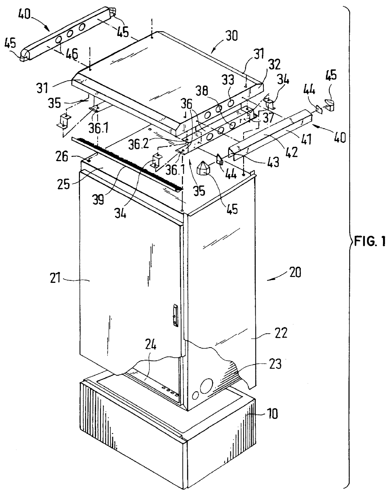
The switchgear cabinet has a cabinet body 20, which is placed on a base 10. The switchgear body 20 can be closed at the front by means of a cabinet door 21. The cabinet body 20 is laterally encased in lateral wall 23. An exterior wall 22 has been doubled at a distance from the lateral walls 23. In this way a ventilation shaft is created between the exterior wall 22 and the lateral wall 23. The ventilation shaft is open near the transition area towards the base 10.

The cabinet body 20 is closed at the top by means of a sheet metal cover 25. In its corner areas, the sheet metal cover 25 has openings providing access to transport receivers 26. The transport receivers 26 are installed in a frame 24 of the cabinet body 20.

A cover 30 can be placed on the sheet metal cover 25. The cover 30 has a level cover section, from which lateral elements 32 are beveled off at the sides. The cover 30 has a projection 31 at the front and the rear. The projection 31 extends over the front, or respectivel...


PUM


Abstract

A switchgear cabinet with a cabinet body and a cover, wherein the cover projects with lateral shoulders past the lateral walls of the cabinet body, which extend in a direction of a cabinet depth of the cabinet body. Joining another switchgear cabinet adjacent a first switchgear cabinet is possible with a relatively small cost, if the lateral walls are embodied as separate elements and can be interchangeably connected with the cover or the cabinet body.

Description

1. Field of the InventionThis invention relates to a switchgear cabinet with a cabinet body and a cover, wherein the cover projects with lateral shoulders past the lateral walls of the cabinet body, which extend in a direction of a cabinet depth.2. Description of Prior ArtSwitchgear cabinets of this type are often employed at locations which are exposed to environmental elements. In this case the lateral walls act as water sluices, which lead the water running down from the cover away. If several switchgear cabinets need to be placed side by side, the individual covers have to be removed and exchanged for a cover extending over all lateral walls. The individual covers are no longer needed.Therefore, expansion of an existing switchgear cabinet by adjoining it with others is very expensive.It is one object of this invention to create a switchgear cabinet of the type mentioned above wherein it is possible with little outlay to join another switchgear cabinet to it.In accordance with th...

Claims


Application Information

Patent Timeline
IPC IPC(8): H02B1/30H02B1/50H02B1/56H02B1/00
CPCH02B1/30H02B1/565H02B1/50H02B1/308
Inventor SCHNEIDER, THOMASDIEBEL, MICHAEL
Owner RITTALWERK RUDOLF LOH GMBH & CO KG
Why Eureka
Try Eureka