Reinforced optical fiber cable of unitube structure

a technology of reinforced optical fiber and unitube, which is applied in the direction of optics, fibre mechanical structures, instruments, etc., can solve the problems of high cost of cable, liable to affect the fibers contained in said protective tubes, and stress can be generated

Inactive Publication Date: 2000-07-18
DRAKA COMTEQ BV
View PDF10 Cites 66 Cited by
  • Summary
  • Abstract
  • Description
  • Claims
  • Application Information

AI Technical Summary

Benefits of technology

the corrugated tubular structure is constituted by a transversely corrugated metal strip that is deformed longitudinally into a tube, or is made of a plastics material and is extruded;
the reinforcing elements include a reinforcing layer between said corr

Problems solved by technology

The differences between the materials of the protective tube and of the sheath in particular mean that stresses can be generated while the extruded sheath is cooling, which stresses are then transmitted to the prot

Method used


Image

  • Reinforced optical fiber cable of unitube structure

Examples


Embodiment Construction

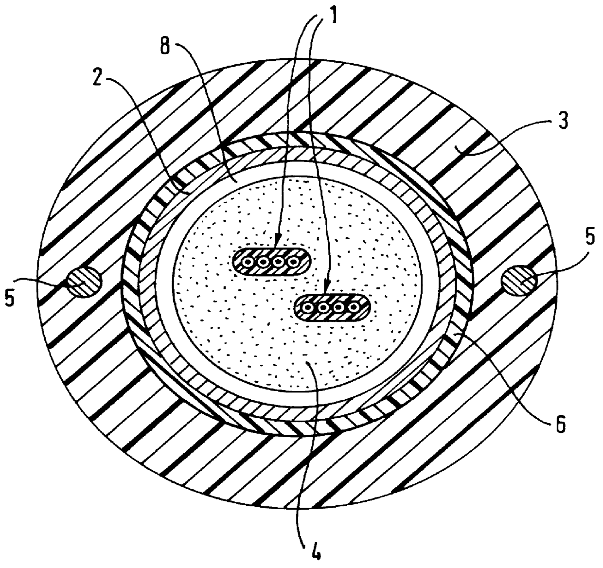
In the embodiment shown, the cable has cords or rods 5 that are relatively stiff and that have high traction strength, which are embedded in the sheath, parallel to the axis of the cable. By way of example, these cords may be made of reinforced plastics material or of steel. There are two such cords in the embodiment shown, in which they are opposite each other. In a variant, there could be four of them, in which case they would be symmetrical in pairs about a diametral plane of the cable being at a small distance from said plane.

The cable advantageously also includes a reinforcing layer 6 between the tubular structure 2 and the outer sheath 3. This reinforcing layer may be constituted by wires or elements having high traction strength, e.g. made of aramid, glass fibers, or FRP material, which are wound helically around the corrugated tubular structure 2. In a variant, the reinforcing layer may also be constituted by an annular layer extruded around the corrugated tubular structure ...


PUM


Abstract

The reinforced optical fiber cable of unitube structure comprises a protective tube for protecting optical fibers, a reinforcing layer, and reinforcing cords, together with an outer sheath around the protective tube. In the cable the protective tube is of corrugated tubular structure. Such a cable is particularly suited for use as a long distance transmission cable.

Description

The present invention relates to a reinforced optical fiber cable of unitube structure comprising a protective tube containing the optical fibers, reinforcing elements around the protective tube, and an outer sheath.Such a cable is intended in particular for long distance data transmission.Document EP-A-0 696 750 discloses a cable of that type, in which the optical fibers, whether independent from one another or assembled together in at least one ribbon, are contained inside a protective tube of plastic together with a filler material for filling the tube. The reinforcing elements of the tube are made of a plastics material that is reinforced by reinforcing fiber and known as FRP material, and they are cabled on the protective tube by being assembled to one another. The outer sheath of the tube is extruded over the reinforcing elements once they are in place.To manufacture such a cable, the optical core defined by the protective tube containing the optical fibers and the filler mate...

Claims


Application Information

Patent Timeline
IPC IPC(8): G02B6/44
CPCG02B6/4432G02B6/4433G02B6/4486
Inventor ELISSON, PETERPABORN, JORGEN
Owner DRAKA COMTEQ BV
Why Eureka
Try Eureka