Hydraulic torque impulse generator

a technology of impulse generator and hydraulic torque, which is applied in the direction of fluid couplings, sealing, couplings, etc., can solve the problems of 0-ring seal, difficult to get completely fluid tight, and large known fluid volume compensating devices, etc., and achieves long and safe service life.

Inactive Publication Date: 2000-08-29
ATLAS COPCO TOOLS AB
View PDF20 Cites 29 Cited by
  • Summary
  • Abstract
  • Description
  • Claims
  • Application Information

AI Technical Summary

Benefits of technology

It is the primary object of the invention to provide a hydraulic torque impulse generator having a compensating device for occurring fluid volume changes that is completely fluid tight, structurally simple and compact and having a long and safe service life.

Problems solved by technology

This known fluid volume compensating device is rather bulky and difficult to get completely fluid tight due to the movable seals.
Also in this impulse generator, the compensation piston is fitted with 0-ring seals which are difficult to get completely fluid tight.
This means that after some period of operation, hydraulic fluid has leaked past the piston seals and filled up the spaces on both sides of the piston with fluid, thereby making the volume compensating device inoperable.
A serious problem inherent in this device is the poor resistance of foamed plastic material against destructive influence of hydraulic fluid.
The service life of this type of volume compensating devices is rather short, since the very thin walls of the closed cells do not withstand for very long the aggressive environment formed by the hydraulic fluid.
After collapse of the closed cells the foamed material will just get soaked by the hydraulic fluid and will not provide any elasticity.

Method used


Image

  • Hydraulic torque impulse generator
  • Hydraulic torque impulse generator
  • Hydraulic torque impulse generator

Examples


Embodiment Construction

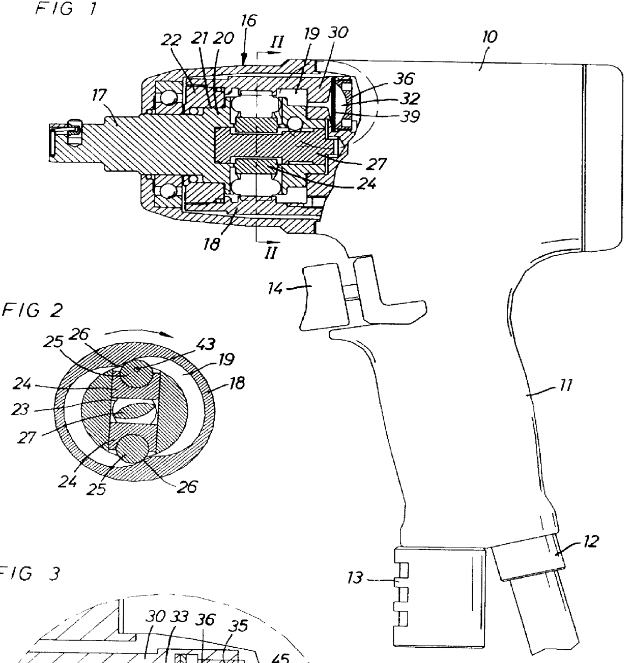
In FIGS. 1, 2 and 3 there is shown a pneumatic power wrench comprising a housing 10 formed with a handle 11, a pressure air supply connection 12 and an exhaust deflector 13 located on the lower extreme end of the handle 11, and a throttle valve 14 for controlling the motive air supply to the wrench.

The power wrench further comprises a pneumatic rotation motor (not shown) connected to the air supply connection 12 as well as to the exhaust deflector 13. The latter communicates with the motor via the inside area of the housing 10 which forms a part of the exhaust passage through the housing 10. The power wrench also comprises a hydraulic torque impulse generator 16 driven by the motor, and an output shaft 17 for delivering torque impulses to a screw joint to be tightened. For that purpose, the output shaft 17 is formed with a square end for carrying a standard type nut socket.

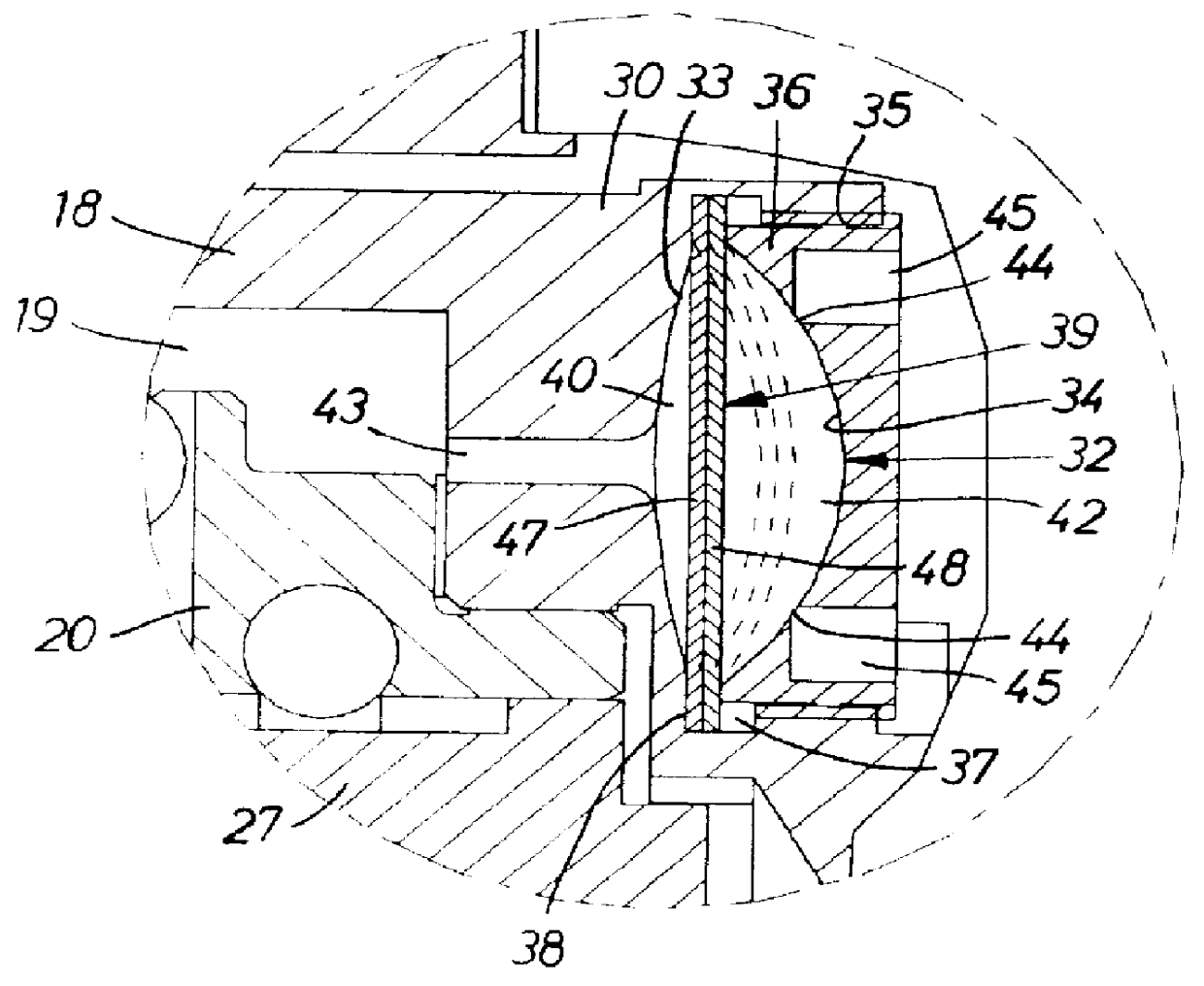
The hydraulic impulse generator 16 comprises a drive member 18 which is connected to the motor and comprises a ...


PUM


Abstract

A hydraulic torque impulse generator (16) of the kind having a motor rotated drive member (18;50) formed with a fluid chamber (19;53), an impulse receiving output member (20;51) coaxial with the drive member (18;50) and extending into the fluid chamber (19;53), a hydraulic peak generating mechanism (24-27;54-59) in the fluid chamber (19;53) for producing torque impulses at relative rotation between the drive member (18;50) and the output member (20;51), and a variable volume accumulator chamber (32;64) located in the drive member (18;50) and connected to the fluid chamber (19;53) for compensating for occurring volume changes in the hydraulic fluid, wherein the accumulator chamber (32:64) is divided into a first compartment (40;71) and a second compartment (42;72) by an elastically deflectable membrane (39;73), a passage (43;65) connects the first compartment (40;71) to the fluid chamber (19;53), and the second compartment (42;72) comprises at least partly a yeildable means for biassing the membrane (39;73) toward the first compartment (40;71), and a closure unit (36;66,68) is arranged to form a clamping means for retaining the membrane (39;73) and for forming partly the accumulator chamber (32;64).

Description

This invention relates to a hydraulic torque impulse generator of the kind having a motor rotated drive member formed with a fluid chamber, an impulse receiving output member coaxial with the drive member and extending into the fluid chamber, a hydraulic pressure peak generating means in the fluid chamber for producing torque impulses at relative rotation between the drive member and the output member, and a variable volume fluid accumulator chamber located in the drive member and connected to the fluid chamber for compensating for occurring volume changes in the hydraulic fluid.An impulse generator of this type is previously described in U.S. Pat. No. 4,789,373. In this prior art impulse generator, an annular accumulator chamber is located in a coaxial relationship with the output shaft and communicating with the fluid chamber via the clearance seal arround the output shaft. An annular piston is reciprocable in this chamber and is provided with 0-rings to seal off the accumulator c...

Claims


Application Information

Patent Timeline
Patent Type & Authority Patents(United States)
IPC IPC(8): B25B21/02
CPCB25B21/02Y10S277/926
Inventor SCHOEPS, KNUT CHRISTIAN
Owner ATLAS COPCO TOOLS AB
Why Eureka
Try Eureka