Bag discharge apparatus

a technology of bag discharge and bag body, which is applied in the direction of power operated devices, applications, and opening closed containers, etc., can solve the problems of slow raising of bags to a limited extent, adversely affecting the discharge, and impede the effective discharge of materials

Inactive Publication Date: 2000-10-31
SPIROFLOW
View PDF17 Cites 15 Cited by
  • Summary
  • Abstract
  • Description
  • Claims
  • Application Information

AI Technical Summary

Problems solved by technology

However, the neck of the container is often narrow and the neck can tend to stay bunched up once the neck is untied and impede the effective discharge of material.
However, the spring means are dependent upon the weight of material in the bag and, as that weight slowly decreases, the spring means slowly raises the bag to a limited e

Method used


Image

  • Bag discharge apparatus
  • Bag discharge apparatus
  • Bag discharge apparatus

Examples


Embodiment Construction

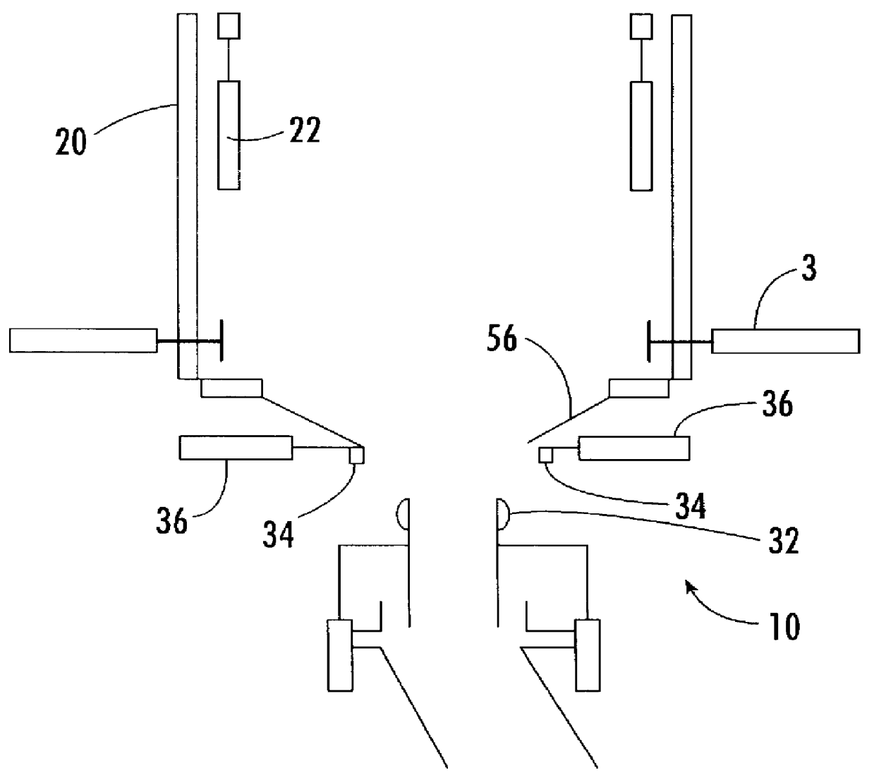
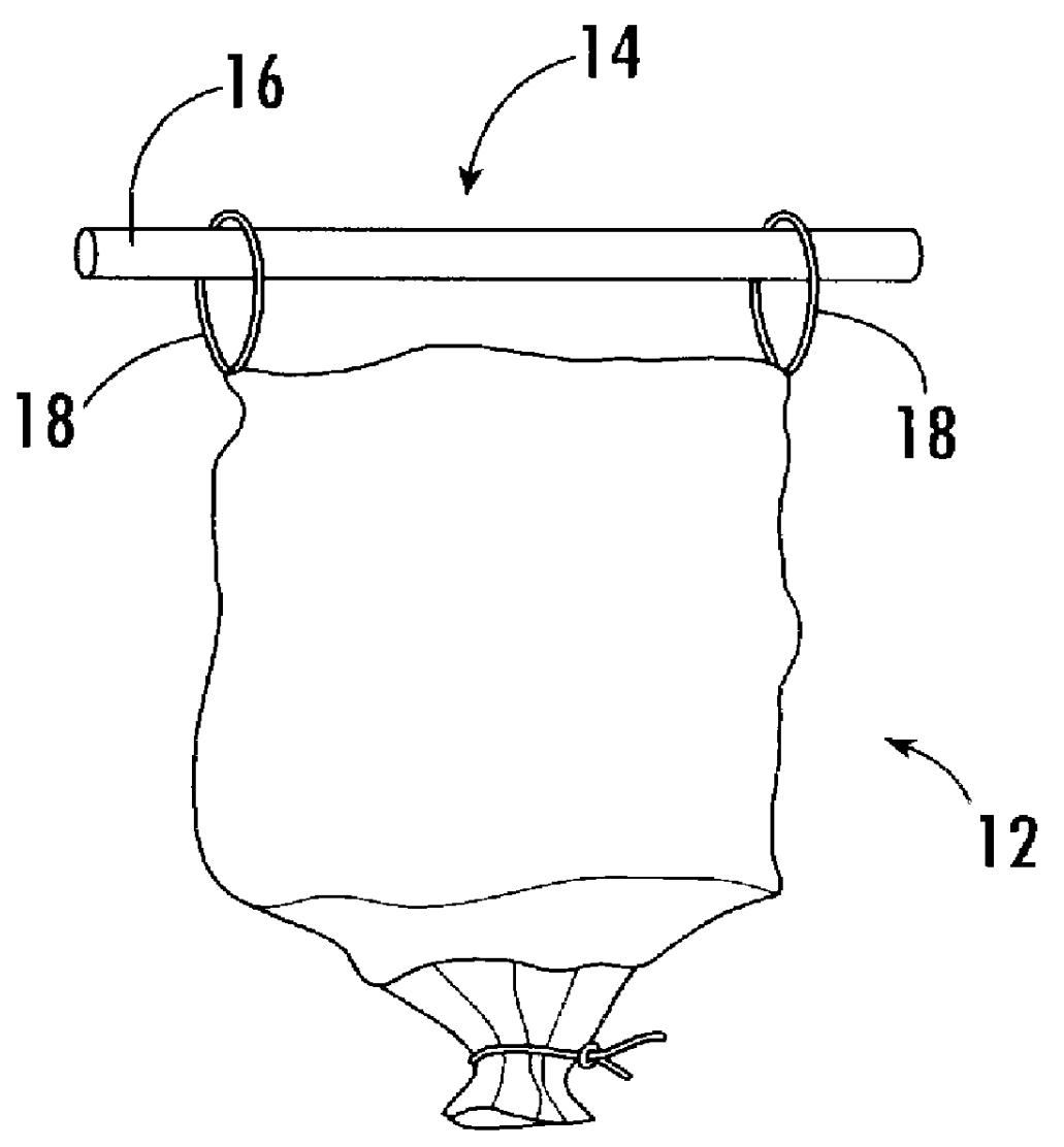
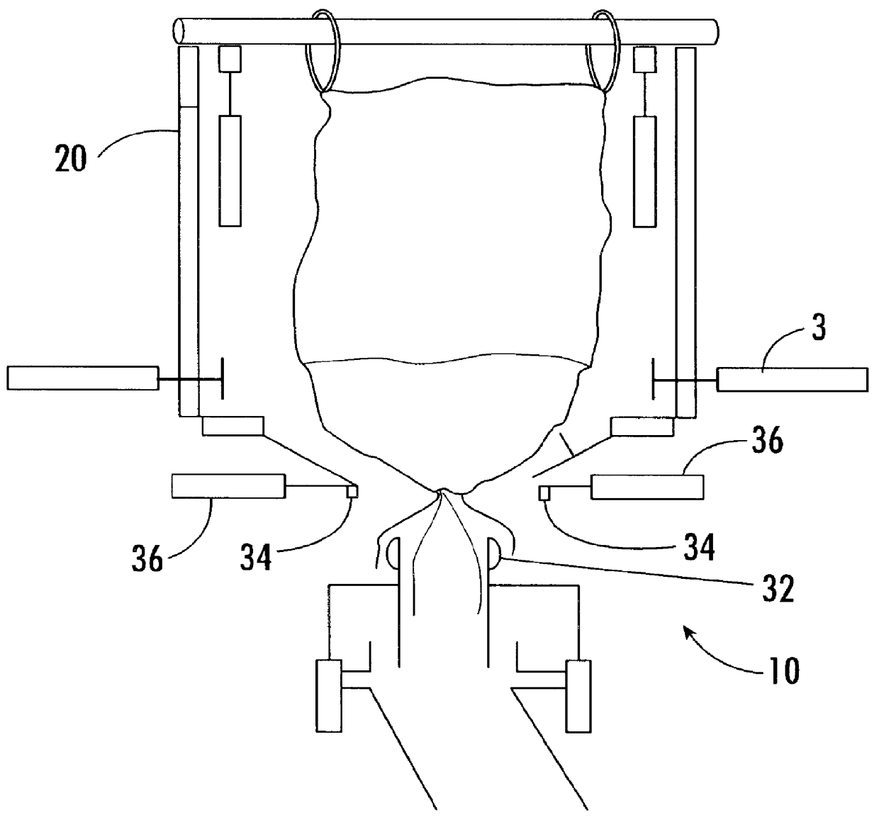
The container 12 shown in FIG. 2 is suspended from spaced parallel bars 16 (only one of which is shown) which are connected together by spaced parallel bars (not shown) that extend inwardly of and perpendicular to the bars 16. Prior to the container being located over the emptying apparatus the container is rigged on to the frame comprised by the bars by passing four loops 18 over each protruding end of the bars 16. A fork lift truck or hoist then engages the frame by the forks extending under the frame 14 between two opposed pairs of loops 18 with the fork then being raised to support the frame with the container 12 being suspended from the frame. The container is then moved to locate the container over the apparatus 10 before the fork lift or hoist support is lowered to locate the bars 16 on support poles 20 of the emptying apparatus or on pneumatic lift cylinders 22 the purpose of which will be described later.

As shown in FIG. 8, the top of the frame may have a pair of spaced upw...


PUM

PropertyMeasurementUnit
Levelaaaaaaaaaa

Abstract

A tie 24 seals an outer bag 26 and an inner line bag 28 of a container. The inner liner bag 28 is fed into a tubular discharge chute 30 and the tubular end of the outer liner bag is passed over the outside of a chute 30 to extend over an inflatable seal 32. Then two opposed pinch bars 34 on either side of the container, just below the tie 24, are actuated by pneumatic cylinders 36 to move towards each other and to pinch the inner and outer bags 26 and 28 just below the tie. Then a seal 32 is inflated to urge the seal against the inner face of the outer bag. Then the tie 24 is removed and the pinch bars are retracted before moving the chute 30 downwardly by retracting pneumatic cylinders 38 to take the lower end of the outer bag downwardly.

Description

TECHNICAL FIELD AND BACKGROUND OF THE INVENTIONThe present invention relates to bag discharge apparatus and means for discharging a bag.Previous machines for discharging flexible bulk containers comprise supporting the bulk container over a discharge chute sealing the neck to the discharge chute and untying a neck at the bottom of the container to allow material to flow out of the container through the discharge chute. However, the neck of the container is often narrow and the neck can tend to stay bunched up once the neck is untied and impede the effective discharge of material. This is particularly the case where a thin extremely flexible and disposable liner bag is located within a heavy reuseable outer bag.Previous bag discharge machines have also suspended the bag from a support frame with the frame then being supported on spring biased poles and with the bottom of the bag being partially supported on a conical plate. As the weight of the bag on the support frame decreases duri...

Claims


Application Information

Patent Timeline
IPC IPC(8): B65B69/00
CPCB29C47/0026B65B69/0091B29C47/1009B29C47/1054B29C48/10B29C48/286B29C48/2888
Inventor TAYLOR, STEVEN JAMESSWINTON, PETER
Owner SPIROFLOW
Why Eureka
Try Eureka