Switchgear cabinet with a framework

a technology of switchgear and frame, which is applied in the direction of cabinet/cabinet/drawer details, furniture parts, machine supports, etc., can solve problems such as total operating failur

Inactive Publication Date: 2000-12-05
RITTALWERK RUDOLF LOH GMBH & CO KG
View PDF36 Cites 39 Cited by
  • Summary
  • Abstract
  • Description
  • Claims
  • Application Information

AI Technical Summary

Benefits of technology

It is an object of this invention to provide overcoming some

Problems solved by technology

During earthquakes, these rigid connections lead to damage and destruction as a result of the sheari

Method used


Image

  • Switchgear cabinet with a framework
  • Switchgear cabinet with a framework
  • Switchgear cabinet with a framework

Examples


Embodiment Construction

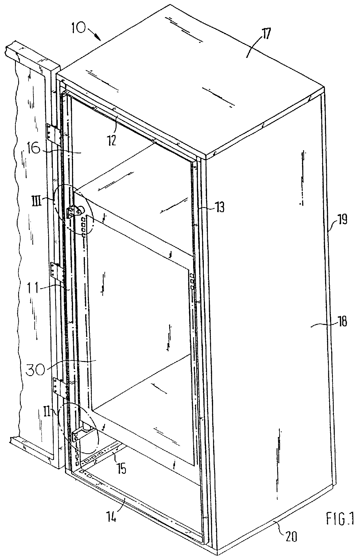
In FIG. 1 only the vertical rack members 11 and 13, the horizontal members 12 and 14 and the lower members 15 of the rack 10 of the switch cabinet can be seen. The rack members can be rigidly connected to each other, e.g., by welding. But they can also be connected to each other by means of corner connectors. Wall elements 16, 17, 18 and 19 close the rack 10, except for the front and bottom side. As shown in FIG. 4, The front side is closed by means of a cabinet door 50. A part of the rack members can also be chamfered at the wall elements 16 to 19. A series of fastening receptacles 33 and / or fastening bore holes 27 are thereby inserted in the rack members.

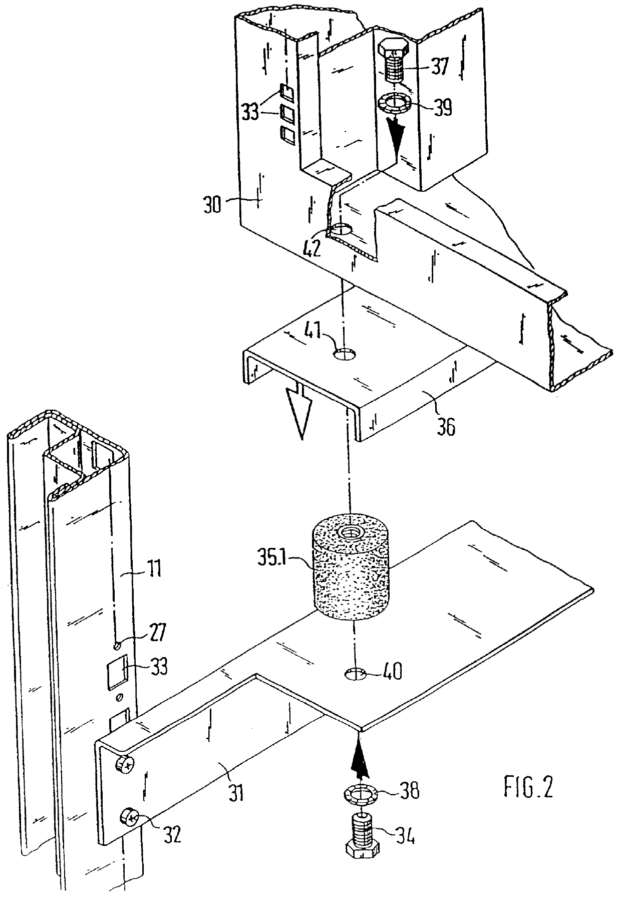
The lower fastening point 11 is shown in FIG. 2 in exploded view. Carrier rails 31 are inserted at both sides between the front and the rear vertical rack members, such as, for example, 11. The carrier rails 31 are fastened with fastening screws 32 to the rack members. Cushioning buffers 35.1 are fastened vertically directed on th...


PUM


Abstract

PCT No. PCT/EP96/00875 Sec. 371 Date Sep. 2, 1997 Sec. 102(e) Date Sep. 2, 1997 PCT Filed Mar. 1, 1996 PCT Pub. No. WO96/28004 PCT Pub. Date Sep. 12, 1996The switchgear cabinet has a framework that is closed or may be closed by wall elements and at least one door. An earthquake-proof mounting of apparatus, mounting plates or the like is achieved in that at least one housing or frame is mounted into the framework. The bottom area of the housing or frame is elastically secured by vertical dampers on horizontal bearing rails arranged between lateral vertical members. The top area of the housing or frame is elastically joined to the vertical members of the framework either directly by means of horizontal dampers or indirectly by means of angle brackets.

Description

This invention is related generally to storage cabinets and, more particularly, to storage cabinets for electronic components.In switch cabinets like the ones used for electronic components, the mounting plates, module supports or the like are rigidly built into the rack. During earthquakes, these rigid connections lead to damage and destruction as a result of the shearing and pulling forces that arises in varying directions and that can lead to total operating failure.It is desirable to store components, especially sensitive electronic components in a cabinet that could protect them from the shock and vibration that results from events such as earthquakes.OBJECTS OF THE INVENTIONIt is an object of this invention to provide overcoming some of the problems and shortcomings of devices of the prior art.Another object of this invention is to provide a switch cabinet that provides earthquake proof protection for components stored within. How these and other important objects are accompli...

Claims


Application Information

Patent Timeline
IPC IPC(8): H02B1/30H02B1/00H02B1/54H05K5/02
CPCH02B1/54H02B1/30
Inventor NICOLAI, WALTER
Owner RITTALWERK RUDOLF LOH GMBH & CO KG
Why Eureka
Try Eureka