Rack for a switchgear cabinet

a switchgear cabinet and rack technology, applied in the field of racks for switchgear cabinets, can solve problems such as obstructing the fastening

Inactive Publication Date: 2000-12-26
RITTALWERK RUDOLF LOH GMBH & CO KG
View PDF24 Cites 32 Cited by
  • Summary
  • Abstract
  • Description
  • Claims
  • Application Information

AI Technical Summary

Problems solved by technology

These support profiles extend over at least two oppositely located frame legs of the lower rack frame and ar

Method used


Image

  • Rack for a switchgear cabinet
  • Rack for a switchgear cabinet
  • Rack for a switchgear cabinet

Examples


Embodiment Construction

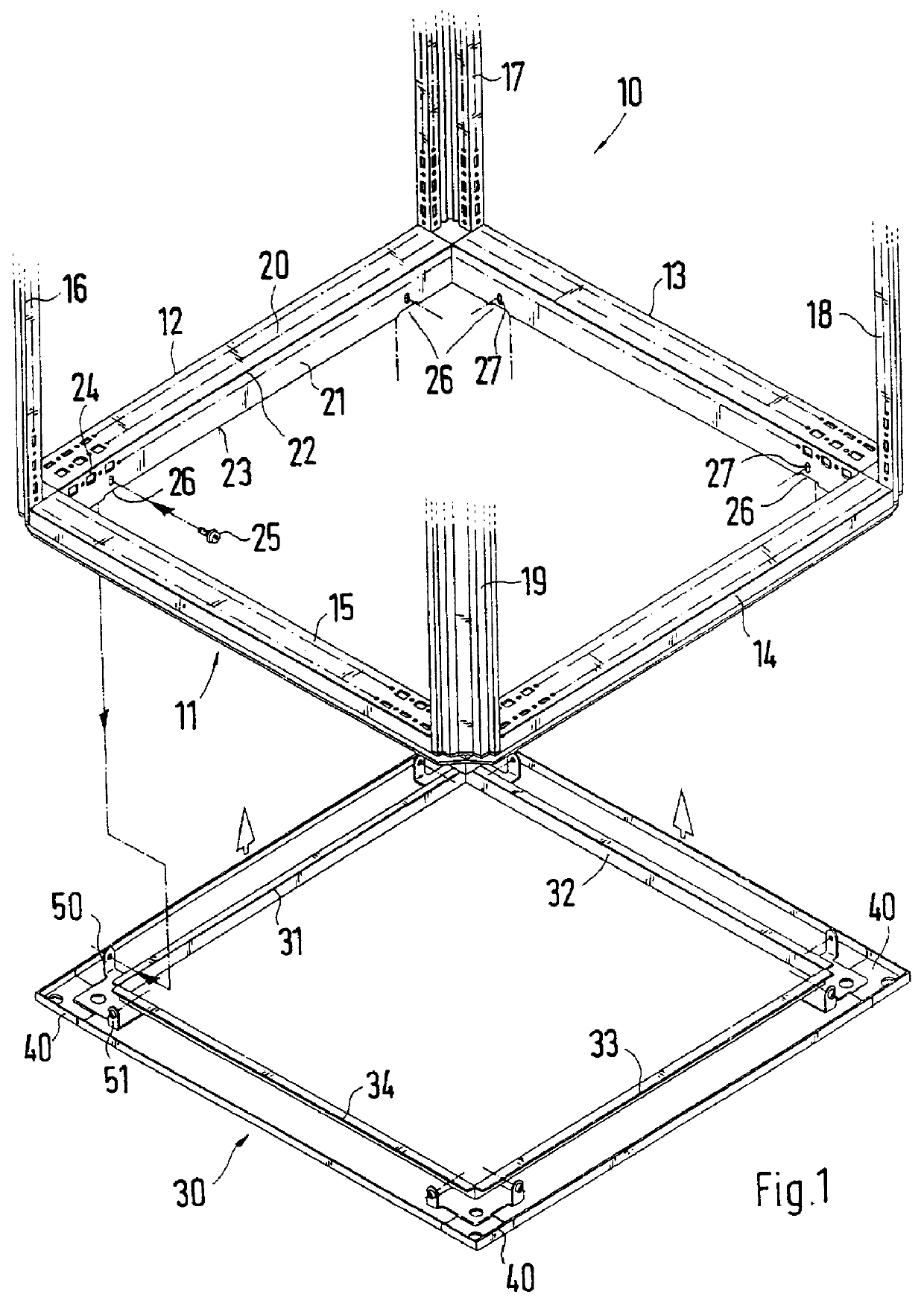
Only the lower part with the lower rack frame 11, which is formed from horizontally oriented frame legs 12, 13, 14 and 15, of the rack 10 of a switchgear cabinet, is shown in FIG. 1. The vertical frame legs 16, 17, 18 and 19 are attached to the corner areas of the rack frame 11, the upper ends of which are connected with an upper rack frame (not shown).

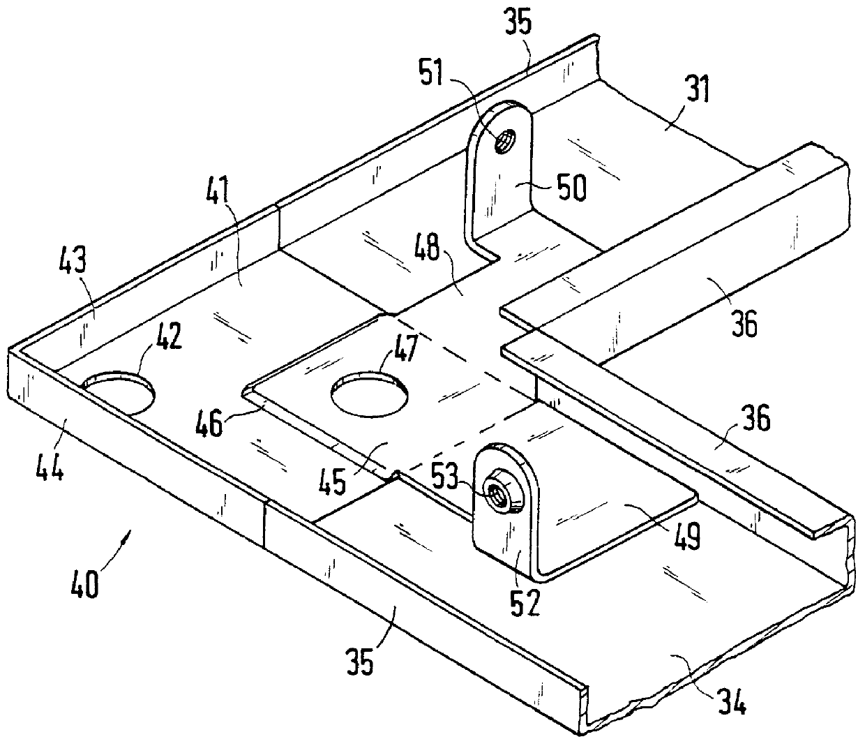
A bottom frame 30 comprises four support profile sections 31 to 34 and four corner pieces 40 and is fastened to the lower rack frame 11 of the rack 10, and in the process comes to lie between the switchgear cabinet base (not shown) and the rack 10.

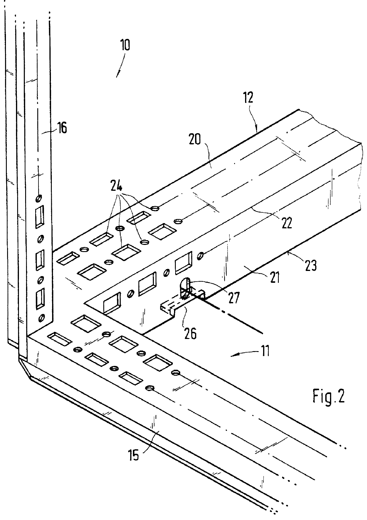
As FIGS. 1 and 2 show, the profile sides 20 and 21 of the frame legs 12 to 15, which are at right angles in relation to each other, form an inner edge 22 of the rack 10 and form rows of system fastening receivers 24. In the area of their lower edge 23 and of the adjoining profile side (not identified in detail), the vertically aligned insides 21 form a recess 26, the width of which is matche...


PUM


Abstract

A rack for a switchgear cabinet, whereby the rack is assembled from frame legs, four of the frame legs being horizontally oriented forming a lower rack frame, which is connected to support profiles for bottom plates. The support profiles form a bottom frame (30), which has upward projecting fastening straps (50, 52). The frame legs (12 to 14) of the lower rack frame (11) have vertically aligned inner profile sides (21), which are provided with recesses (26) in the area of their lower edges (23) and of the adjoining profile sides for introducing the fastening straps (50, 52), and the fastening straps (50, 52) are screwed in place, resting on the inside of these inner profile sides (21) of the lower rack frame (11).

Description

1. Field of the InventionThe invention relates to a rack for a switchgear cabinet, which is assembled from a plurality of frame legs, four frame legs of which are horizontally oriented forming a lower rack frame, which is connected with support profiles for bottom plates.2. Description of Prior ArtA rack of this type is taught by German Patent Publication DE 33 44 598 C1. Here, separate support profiles are screwed to the lower rack frame, to which bottom plates, which are resting on them, can be fastened and which close the open underside of the rack. These support profiles extend over at least two oppositely located frame legs of the lower rack frame and are fastened thereon, as a result of which they obstruct the fastening to these frame legs from one direction. In the two fastening profile sides which are located at right angles to each other and which form an inner edge of the rack, the frame legs have rows of system fastening receivers which, after attachment of the support pr...

Claims


Application Information

Patent Timeline
IPC IPC(8): H02B1/00H02B1/01H02B3/00H02B1/30
CPCH02B1/01H02B1/011
Inventor REUTER, WOLFGANG
Owner RITTALWERK RUDOLF LOH GMBH & CO KG
Why Eureka
Try Eureka