Sliding sleeve assembly for subsurface flow control

a flow control and sliding technology, applied in the direction of fluid removal, sealing/packing, borehole/well accessories, etc., can solve the problems of reducing the service life of the sleeve assembly

Inactive Publication Date: 2001-02-20
WEATHERFORD TECH HLDG LLC
View PDF3 Cites 57 Cited by
  • Summary
  • Abstract
  • Description
  • Claims
  • Application Information

AI Technical Summary

Problems solved by technology

After a well is drilled, it is sometimes necessary to inject pressurized fluid slurries into the well bore to fracture and prop open the resulting cracks formed in the formation.
The solids in the high pressure, rapidly flowing fracturing fluid can quickly erode the pipe and accessories used to pump the fluid into the formation.
The turbulent flow, in turn, when combined with entrained abrasives such as sand can quickly wear away and otherwise damage the pipe and sliding sleeve assembly.

Method used


Image

  • Sliding sleeve assembly for subsurface flow control
  • Sliding sleeve assembly for subsurface flow control
  • Sliding sleeve assembly for subsurface flow control

Examples


Embodiment Construction

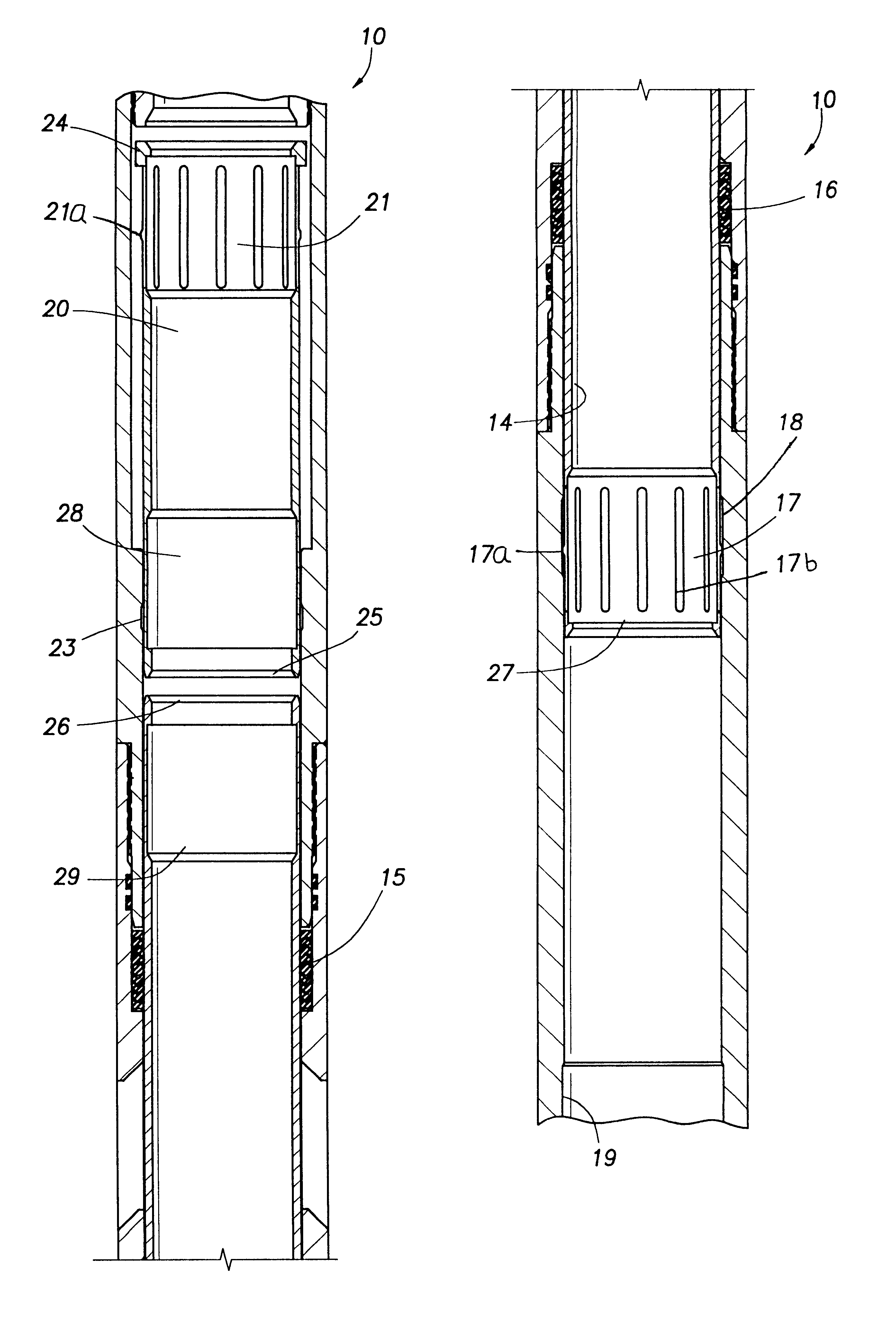
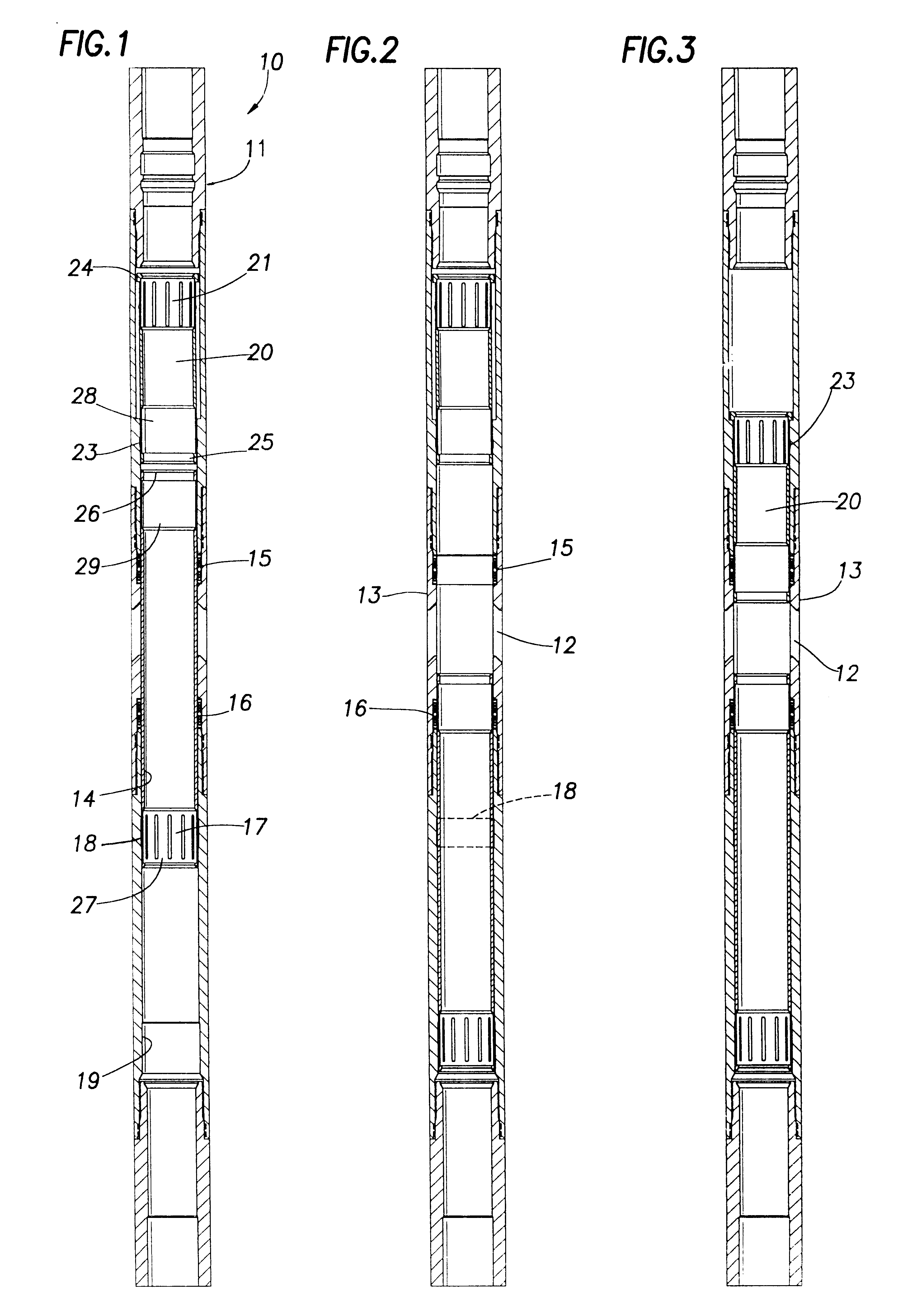
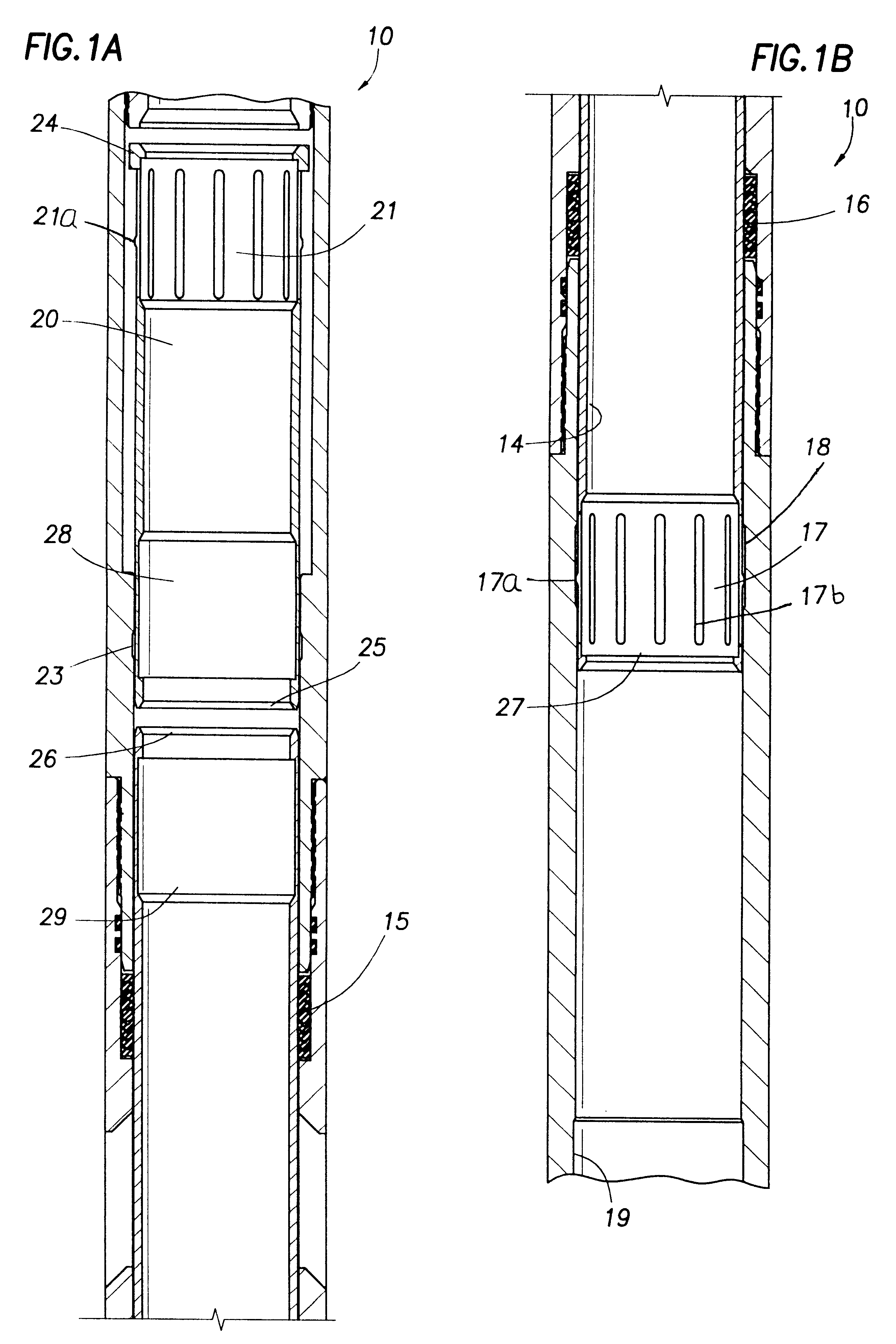
The sliding sleeve assembly of the present invention is indicated generally at 10 in FIG. 1. The assembly 10 is adapted to be employed as part of a tubing string (not illustrated) in a well, extending between a subsurface formation and the well surface. As employed in the present invention, the assembly 10 is used to inject fluid slurries from the tubing string into the subsurface formation to fracture and prop open the formation surrounding the well bore. After the formation has been fractured, the assembly 10 is employed as part of the tubing string to convey well fluids back to the well surface.

The fracturing fluid used to treat the formation is pumped through the tubing string and through a top 11 of the assembly 10. As best illustrated in FIG. 3, fluid entering the assembly 10 at the top 11 exits the assembly through circumferentially spaced, axially and radially extending slots 12 opening through the assembly wall 13. During the fracturing process, the tubing below the assembl...


PUM


Abstract

Two sliding sleeves are carried in a tubular pipe assembly for controlling the opening and closing of flow passages extending through the pipe wall. The pipe assembly is placed at the lower end of a tubing string disposed in a well to regulate the flow of fluid from the string into a subsurface well formation. The first sleeve extends between upper and lower seals disposed above and below the flow passage to close the flow passages to flow. A shifting tool operated from the well surface moves the sleeve axially down through the pipe assembly to open the flow passages, leaving the upper seal exposed. The shifting tool then moves the second sleeve axially down through the pipe to cover the exposed seal. Fluid pumped through the pipe exits freely through the flow passages without first having to flow through radial flow passages in the sliding sleeve to prevent erosion of the flow passages and the sleeve structure. The two sleeve sections protect the upper and lower seals and sealing surfaces from erosion as fluid is pumped.

Description

1. Field of the InventionThe present invention relates generally to means for remotely opening and closing flow passages through a tubular body. More particularly, the present invention relates to means for remotely opening a subsurface flow passage in a pipe string contained within a well bore to inject fracturing slurries into the well formation.2. Description of Prior Art SettingAfter a well is drilled, it is sometimes necessary to inject pressurized fluid slurries into the well bore to fracture and prop open the resulting cracks formed in the formation. The slurry typically is made up of sand particles entrained in a supporting well treating fluid. The particulate matter lodges in the formation cracks created by the high pressure pumping to keep the cracks open after the pumping pressure is reduced. Fracturing and propping open of the formation permits an increase in the flow of the underground petroleum fluids to the well bore. The solids in the high pressure, rapidly flowing f...

Claims


Application Information

Patent Timeline
Patent Type & Authority Patents(United States)
IPC IPC(8): E21B34/00E21B21/00E21B21/10E21B34/14
CPCE21B21/103E21B34/14
Inventor WYATT, MARK L.HUBER, BRAD N.
Owner WEATHERFORD TECH HLDG LLC
Why Eureka
Try Eureka