Garment hanger

Inactive Publication Date: 2001-04-03
LOUW HENRY J
View PDF68 Cites 26 Cited by
  • Summary
  • Abstract
  • Description
  • Claims
  • Application Information

AI Technical Summary

Problems solved by technology

Unfortunately, the prior art size caps and hangers, such as the hanger of the '902 patent, are substantially complex and difficult and costly to manufacture, such as by injection molding or the like.

Method used


Image

  • Garment hanger
  • Garment hanger
  • Garment hanger

Examples


Embodiment Construction

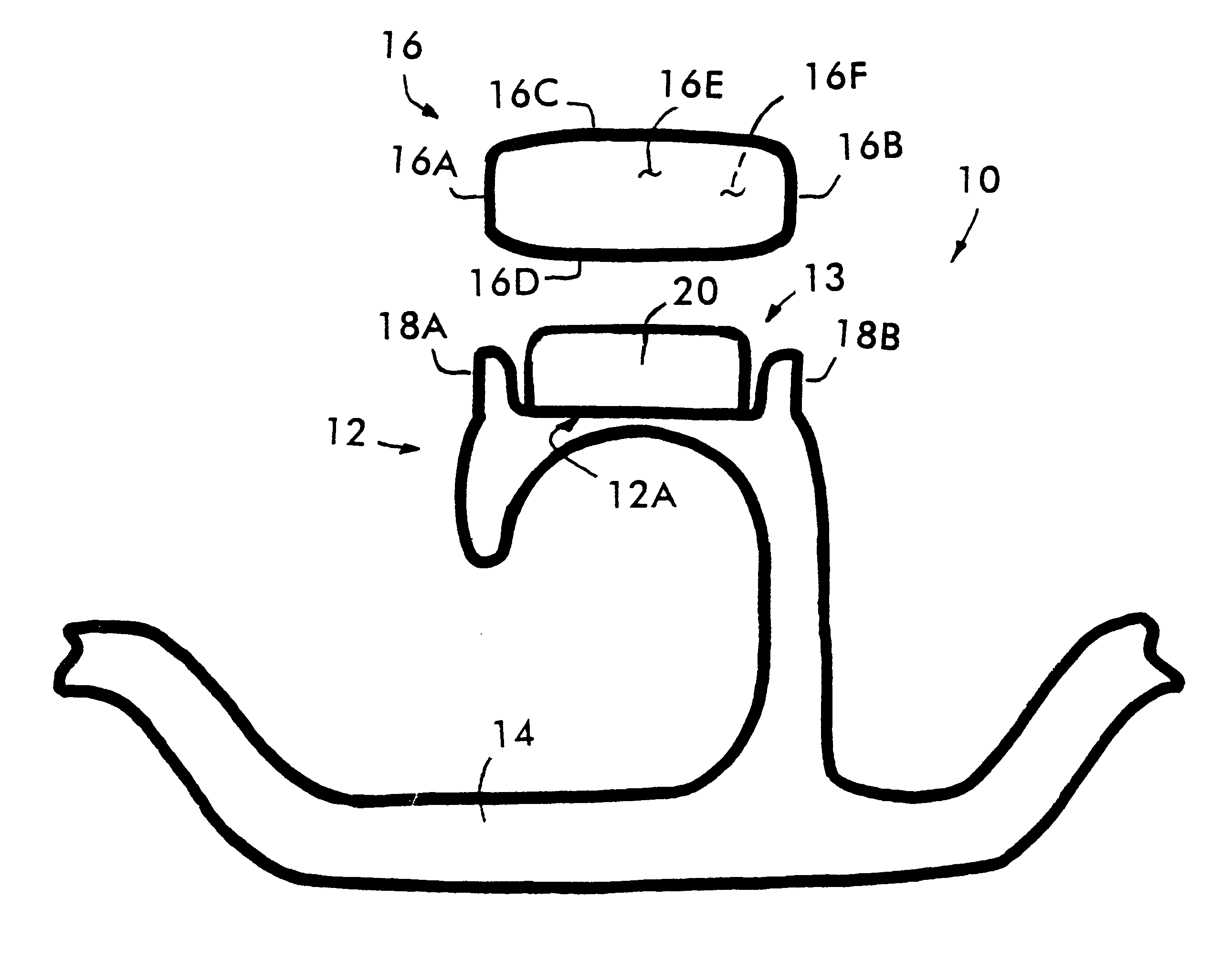
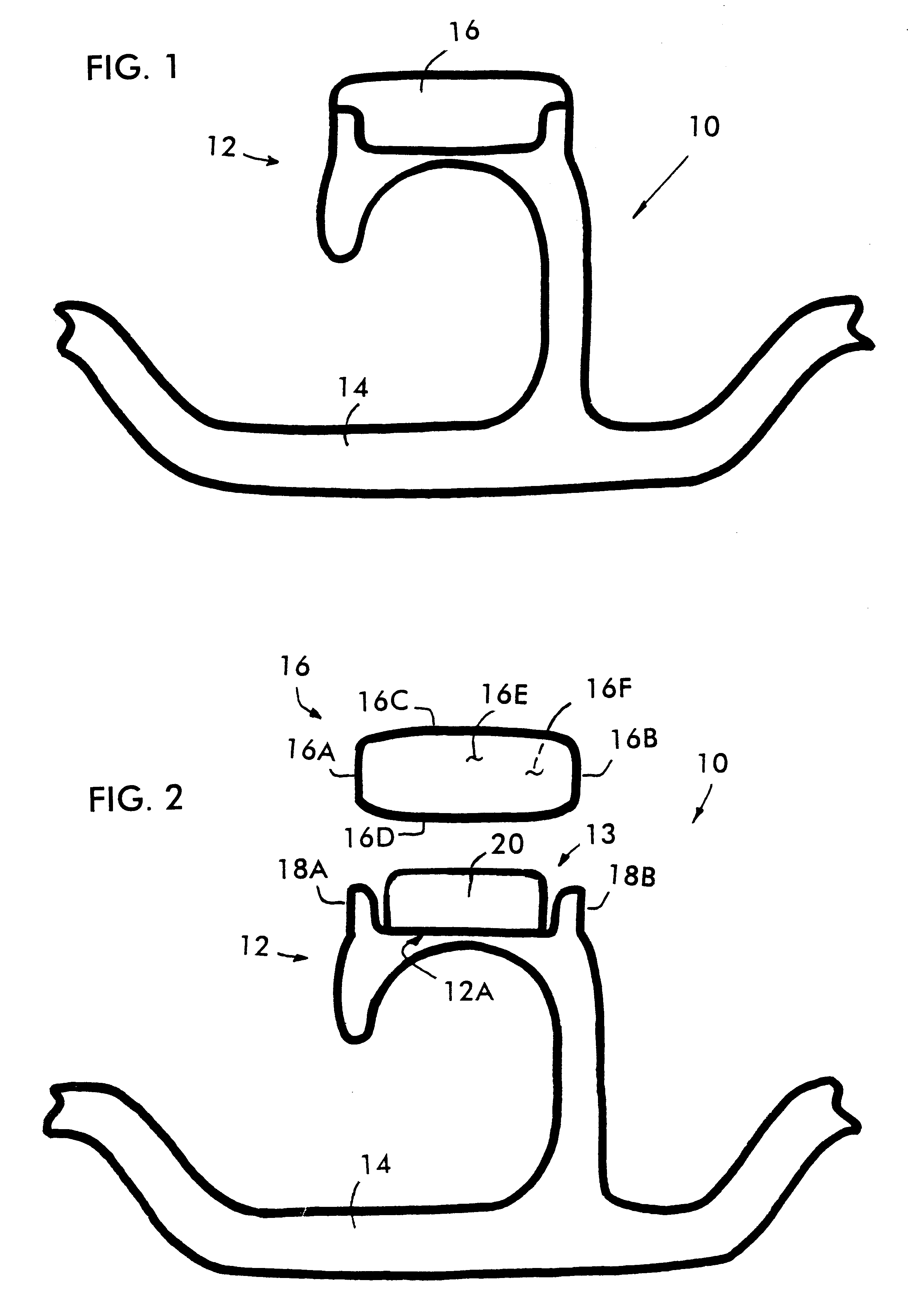
Referring to the drawings wherein like numerals indicate like elements there is shown in FIG. 1 a garment hanger 10 which may be formed from any of the known materials by any of the known techniques. Preferably, garment hanger 10 is made from plastic using an injection molding technique.

Garment hanger 10 includes a suspension hook 12 attached at its lower end to an elongated bar 14. Bar 14 usually includes a garment support means at either end thereof (not shown).

Garment hanger 10 also includes an indicator (or size cap) 16 which is adapted to display any desirable indicia, such as the size of the garment being hung from the hanger 10 and / or the name of the manufacturer.

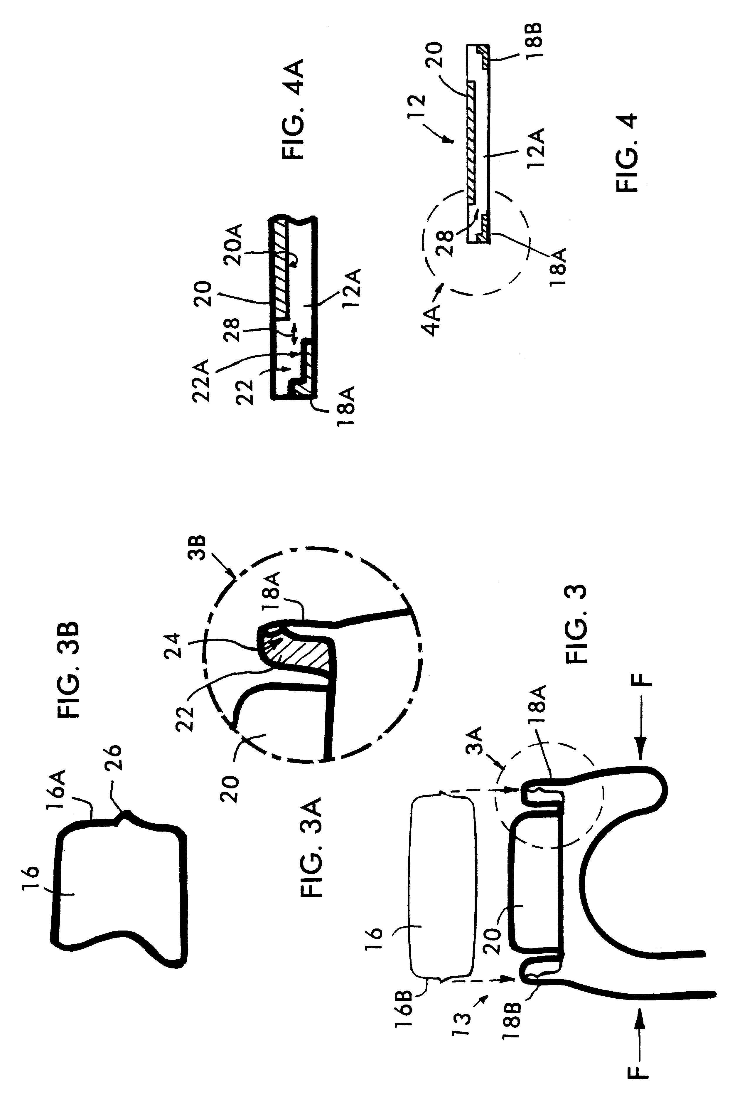
Referring to FIG. 2, size cap 16 includes side edges 16A, 16B, top and bottom edges 16C, 16D and front and rear surfaces 16E, 16F for displaying indicia. Preferably, size cap 16 is in the form of a substantially rectangular and flat plate having a height of about 1 / 2 inch from top edge 16C to bottom edge 16D and a wi...


PUM


Abstract

A hanger includes a suspension hook adapted to engage a hook support and having an upper portion including at least a partial recess; and an indicator having front, rear, side, top and bottom portions, the front portion including a surface for displacing indicia, the partial recess being adapted to releasably receive at least a portion of the side or bottom portions of the indicator such that the indicator is releasably coupled to the suspension hook.

Description

1. Field of the InventionThe present invention relates to improvements in indicators (or size caps) for garment hangers and, more particularly, to indicators which are removably coupled to a top portion of the garment hangers.2. Description of Related ArtVarious types of garment hangers employing size caps are known. For example, U.S. Pat. No. 4,322,902 and its Re-examination Certificate disclose an indicator for a garment hanger having a body portion containing indicia where the body portion includes a means for releasably attaching the indicator to a part of the hanger.The '902 patent also discloses an attaching means having a head shank having two separated portions which are resiliently deformable towards a central cavity to enable the head shank to be inserted into and removed from a slot or other opening formed in a display portion of a hanger.The '902 patent further discloses an indicating device having a shaped body including a wide base, a narrower top and a cavity having a...

Claims


Application Information

Patent Timeline
IPC IPC(8): G09F3/12G09F3/08
CPCG09F3/08G09F3/12A47G25/1421
Inventor LOUW, HENRY J.
Owner LOUW HENRY J
Why Eureka
Try Eureka