
Support for a torch

a technology for supporting a torch and a torch body, which is applied in the direction of lighting support devices, combustion types, lighting and heating apparatuses, etc. it can solve the problems of not being able to use a kind of support in the ground, not being able to be used on a fence as a decoration or for illumination, and not being easy to be inserted into hard ground

Inactive Publication Date: 2001-04-17
YEH JUI JU
View PDF11 Cites 9 Cited by
  • Summary
  • Abstract
  • Description
  • Claims
  • Application Information

AI Technical Summary

Problems solved by technology

Because the spike is crude, it is not easy to be inserted it into hard ground when the weather has been very dry or very cold.
This kind of support can only be used in the ground.
It cannot be used on a fence as a decoration or for illumination.

Method used


Image

  • Support for a torch
  • Support for a torch
  • Support for a torch

Examples


Embodiment Construction

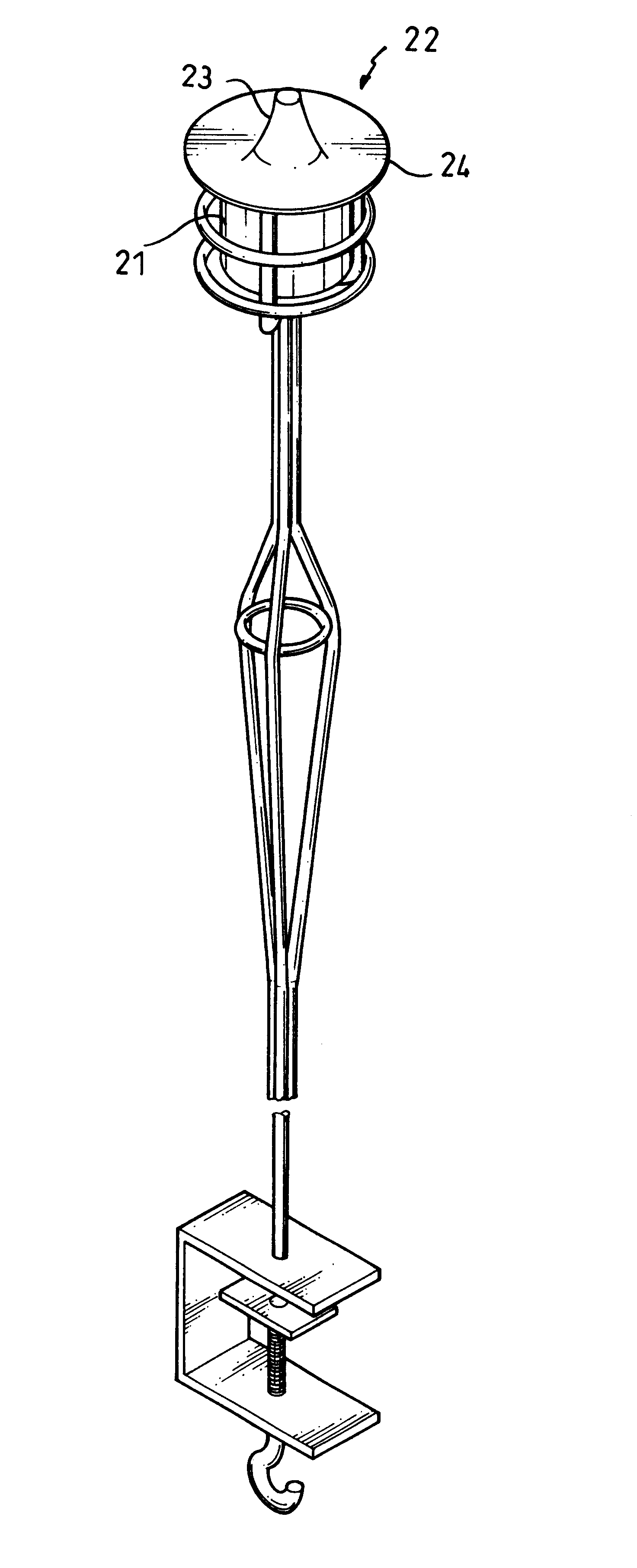
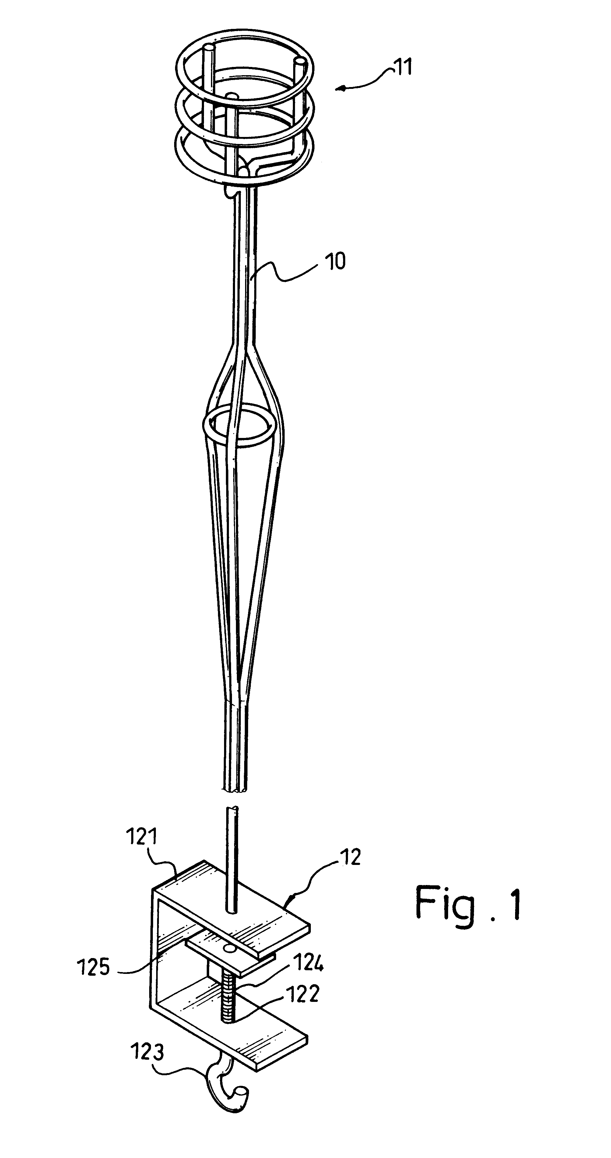
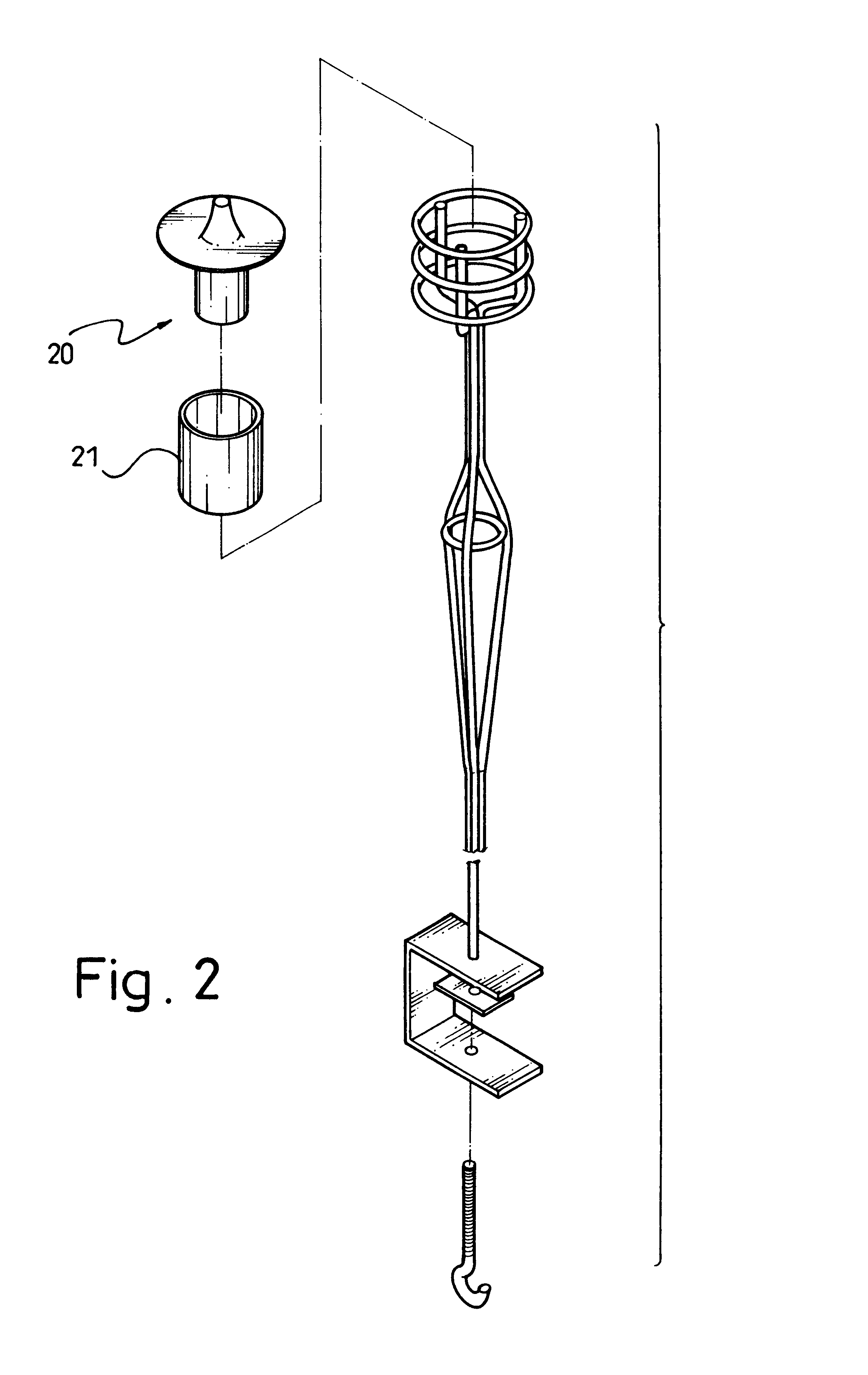
Referring to FIGS. 1 and 2, a support for a torch (not shown) includes a shank (10), a circular torch seat (11) formed on or securely attached to the first distal end of the shank (10) and a retainer (12) securely attached to the second distal end of the shank (10). The circular torch seat (11) is provided to hold a fuel reservoir (20) (as shown in FIG. 2) with a hollow housing (21) mounted outside the fuel reservoir (20) to protect the fuel reservoir (20) from damage and having a closed end (not numbered). The retainer (12) includes a U-shaped bracket (121) with a threaded hole (122) defined therethrough, a handle (123) with a threaded extension (124) screwed through the hole (122) and a backing plate (125) securely attached to the free end of the extension (124).

With reference to FIG. 3 and still taking FIG. 2 for reference, the fuel reservoir (20) has a cover (22) screwed onto the reservoir (20) and is provided with a mouth (23) in the center of the cover (22). Before the fuel re...


PUM


Abstract

A support for a torch is disclosed. The support has a shank, a torch seat formed on the first end of the shank, a retainer provided on the second end of the shank. The retainer has a U-shaped bracket, a through hole defined in a face of the bracket, an extension screwed through the through hole, a handle integrally formed on the first end of the extension and a backing plate securely attached to the second end of the extension. Therefore, a gap defined between the backing plate and the inner face of the bracket is able to be adjusted by rotating the extension so as that the retainer is able to clamp an object to stand the support in an upright position.

Description

1. Field of the InventionThe present invention is related to a support for a torch and more particularly to a support providing good rigidity and safety.2. Description of Related ArtOutdoor activities at night, such as concerts, evening picnics, etc. are becoming increasingly popular, and torches are an attractive device to illuminate the area. The torches must be held at a height that enables maximum illumination and safety. A conventional support for a torch comprises a shank, a frame on the top of the shank to contain a fuel case and a spike at the bottom end of the shank to be stuck into the ground.Because the spike is crude, it is not easy to be inserted it into hard ground when the weather has been very dry or very cold.A conventional torch stand is shown in the Fig.5. To obviate the aforementioned problem, a rail (92) is provided at a suitable position on the shank (90) so the user can easily press the rail (92) with a foot in order to drive the spike into the ground until th...

Claims


Application Information

Patent Timeline
Patent Type & Authority Patents(United States)
IPC IPC(8): F16M13/02F21V21/08F21V21/088F21L17/00F21V21/10
CPCF16M13/02F21L17/00F21V21/088F21V21/10F16M13/022F21V21/116
Inventor YEH, JUI-JU
Owner YEH JUI JU
Learn More