Pillar unit

a technology for pillars and units, applied in the direction of vehicular safety arrangements, pedestrian/occupant safety arrangements, vehicle components, etc., can solve the problems of excessive stress on the bolt securing portion, garnish to be pressed, and foregoing pillar garnish broken

Inactive Publication Date: 2001-05-22
INOAC CORP
View PDF2 Cites 45 Cited by
  • Summary
  • Abstract
  • Description
  • Claims
  • Application Information

AI Technical Summary

Problems solved by technology

Therefore, excessively large stress is exerted on the bolt securing portion when expansion of the air bag causes the side portion of the pillar garnish to be pressed and bent.
Thus, there is apprehension that the foregoing pillar garnish is broken.
Therefore, the head of the bolt appears on the designed side of the pillar garnish, causing the appearance to deteriorate.
The blind cover portion is, however, easily recognized, causing the appearance to deteriorate.
Thus, occurrence of the sink mark cannot be prevented.

Method used


Image

  • Pillar unit
  • Pillar unit
  • Pillar unit

Examples


first embodiment

(First embodiment)

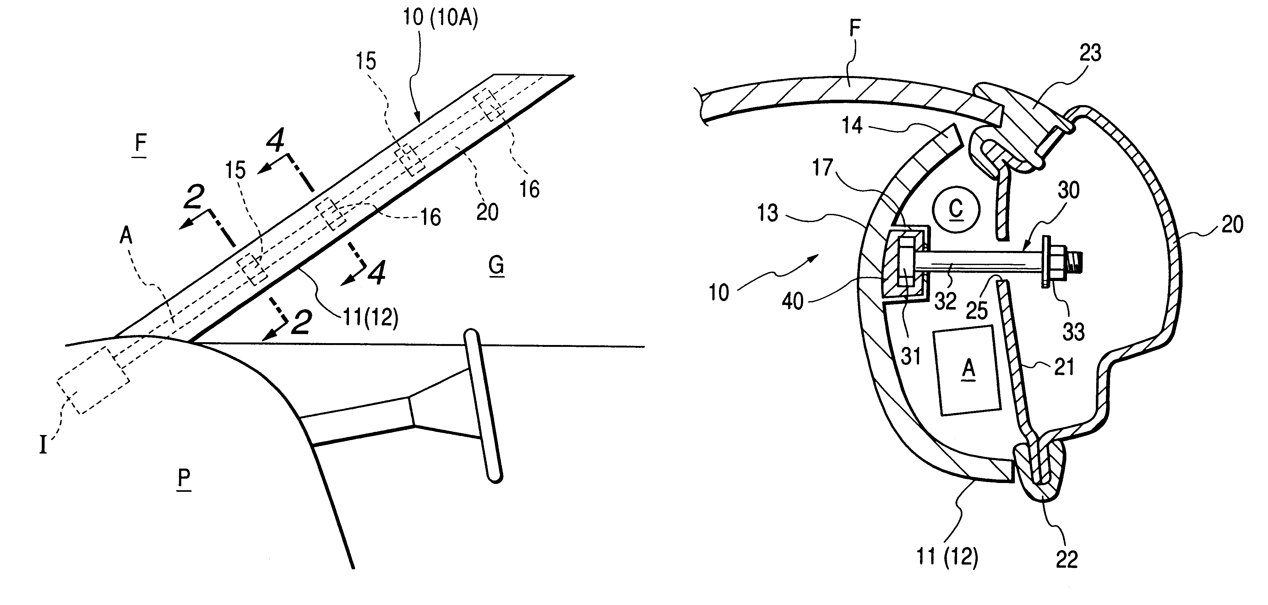
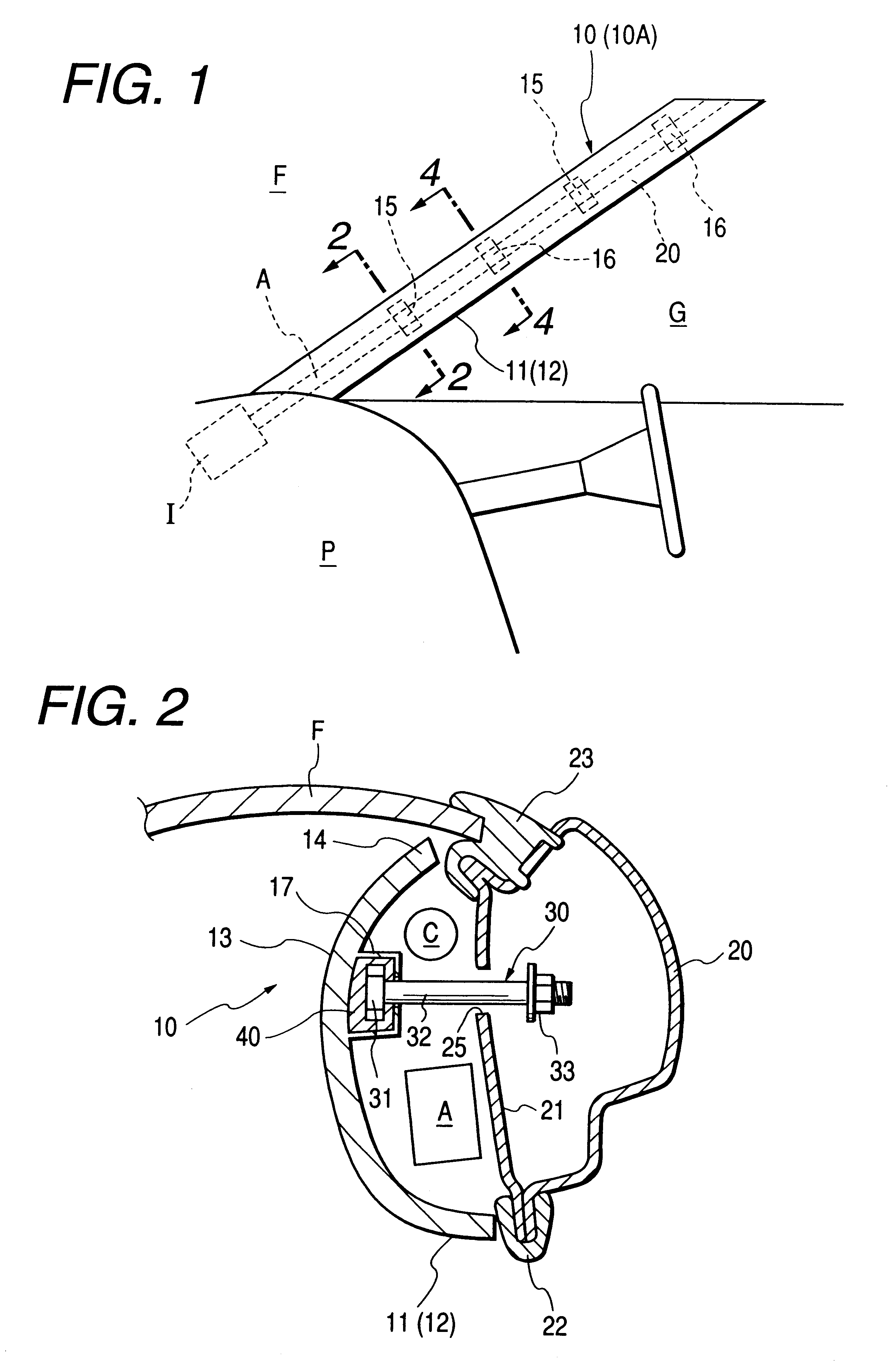
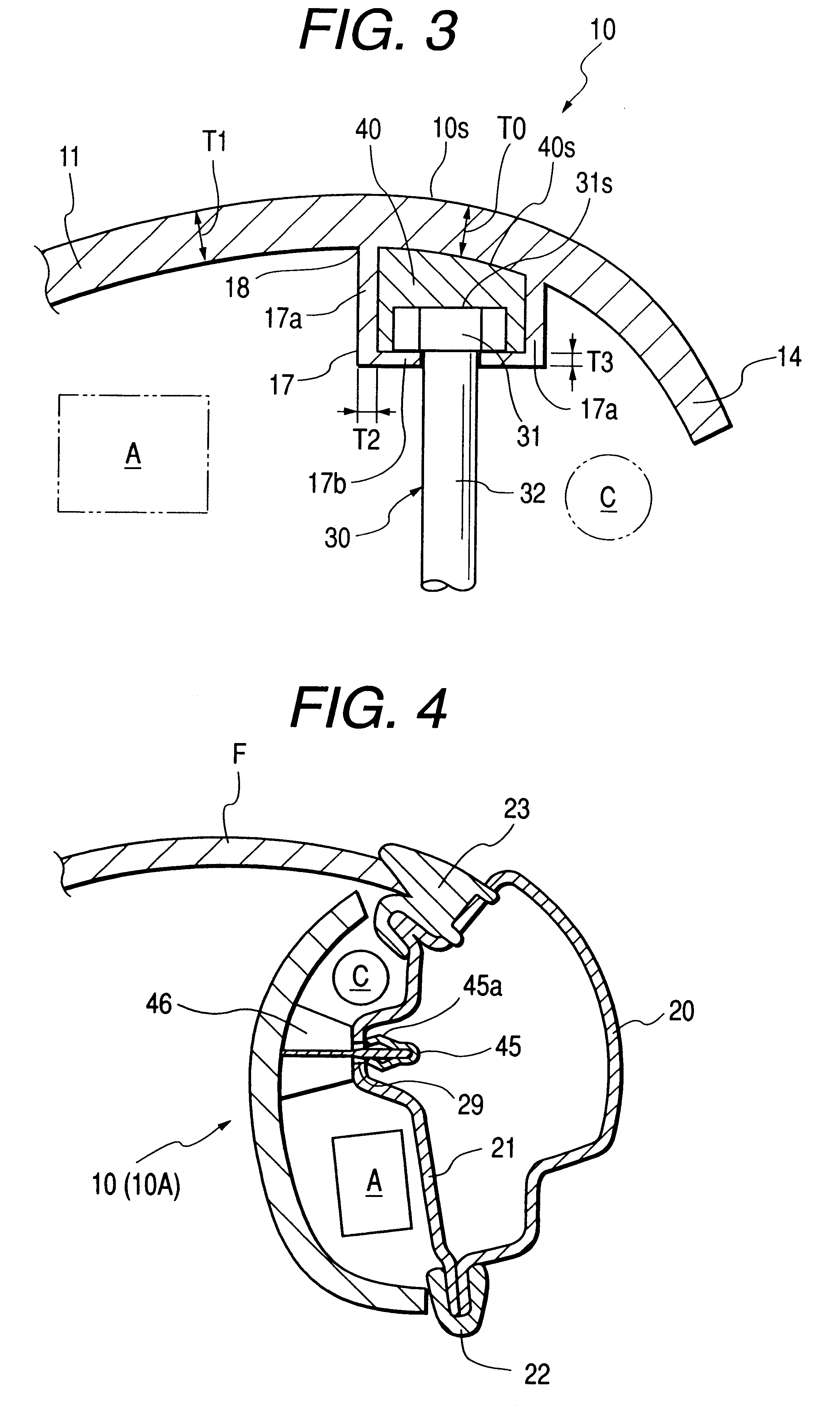
FIG. 1 is a schematic view showing the inside portion of a cabin to which a pillar garnish has been joined by the joining structure according to the present invention. FIG. 2 is a cross sectional view taken along line 2--2 shown in FIG. 1. FIG. 3 is an enlarged cross sectional view showing a portion in the vicinity of the rod-shape fixing metal member shown in FIG. 2. FIG. 4 is a cross sectional view taken along line 4--4 shown in FIG. 1. FIG. 5 is a partial and perspective view showing a state in which the pillar garnish shown in FIG. 1 is joined. FIG. 6 is a cross sectional view showing a structure in which a bottom surface of a seat portion is omitted. FIG. 7 is a perspective view showing another example of the rod-shape fixing metal member. FIG. 8 is a cross sectional view taken along line 2--2 shown in FIG. 1. FIG. 9 is a cross sectional view showing a portion in the vicinity of the rod-shape fixing metal member shown in FIG. 8. FIG. 10 is a bottom view showin...

second embodiment

(Second embodiment)

The second embodiment of the present invention will be described in detailed as follows referring to FIGS. 1 and 12 to 18. The descriptions which have been described in the first embodiment are omitted from the descriptions of the second embodiment.

FIG. 12 is a cross sectional view taken along line 2--2 shown in FIG. 1. FIG. 13 is a cross sectional view taken along line 3--3 shown in FIG. 1. FIG. 14 is a partial and perspective view showing a state in which the pillar garnish is joined. FIG. 15 is a cross sectional view showing the pillar garnish when an air bag has been expanded. FIG. 16 is a graph of DSC. FIG. 17 is a perspective view showing another example of a covering member. FIG. 18 is a cross sectional view showing another embodiment of the present invention.

As shown in FIG. 12, the outer surface of the side portion of the shaft portion 132 of the rod-shape fixing metal member 130 is covered with a cylindrical covering member 140 made of adequate metal or ...


PUM


Abstract

A structure for joining a pillar garnish including an air bag, incorporating: a pillar garnish 10 made of synthetic resin and having a reverse side from which a seat portion 17 projects into which a head 31 of a rod-shape fixing metal member 31 is embedded; and an engaging portion 33 formed at another end of the rod-shape fixing metal member and inserted and engaged into the inside portion of an engaging hole 25 of a pillar portion of the car body, wherein the head 31 of the rod-shape fixing metal member 30 is covered with a coating layer 40 made of synthetic resin to make the thickness of the pillar garnish surrounded by the side surface of the seat portion to be uniform, the resin for constituting the coating layer contains polyolefine by 40 wt % or greater and having the relationship between peak area S1 which indicates a heating value required to melt polypropylene and detected by differential scanning calorie measurement (DSC) and peak area S2 indicating a heating value required to melt a component which is melted at a temperature lower than the temperature at which polypropylene is melted, the relationship satisfying S2/S1<½.

Description

1. Field of the InventionThe present invention relates to a pillar garnish which is joined to a front pillar portion of an automobile, and more particularly to a structure for joining a pillar garnish including an air bag.2. Description of the Related ArtHitherto, passengers of an automobile are safely protected from a shock caused from collision by an air bag apparatus provided for the front portion and side portions in the cabin. To prevent collision of the head of a passenger with a side glass or the like in the event of a shock exerted from the side surface of an automobile, a pillar garnish 60 including an air bag A on the reverse side thereof is, in recent years, joined to a pillar portion 75 of the front portion of the car body, as shown in FIG. 19. The pillar garnish 60 including the air bag is structured such that an inflater I disposed adjacent to an instrument panel P generates gas with which the air bag A is expanded as shown in FIG. 20. Thus, the air bag A is expanded, ...

Claims


Application Information

Patent Timeline
Patent Type & Authority Patents(United States)
IPC IPC(8): B60R21/20B60R21/16B60R21/213B60R21/231B60R21/232
CPCB60R21/213B60R21/232B60R21/23138
Inventor IWANAGA, KENTARO
Owner INOAC CORP
Why Eureka
Try Eureka