Switching cabinet

a technology for switching cabinets and hinges, applied in the field of switching cabinets, can solve the problems of high limit on the accessibility of individual units, and the unnecessary of complicated measures to seal the hinge connection sites

Inactive Publication Date: 2001-05-29
RITTALWERK RUDOLF LOH GMBH & CO KG
View PDF9 Cites 57 Cited by
  • Summary
  • Abstract
  • Description
  • Claims
  • Application Information

AI Technical Summary

Problems solved by technology

The switching cabinets are often tightly occupied so that the accessibility to individual units is highly limited.
Because the fact that the hinges are arranged outside of the sealing area, complicated measures to seal the hinge connection sites become unnecessary.

Method used


Image

  • Switching cabinet
  • Switching cabinet
  • Switching cabinet

Examples


Embodiment Construction

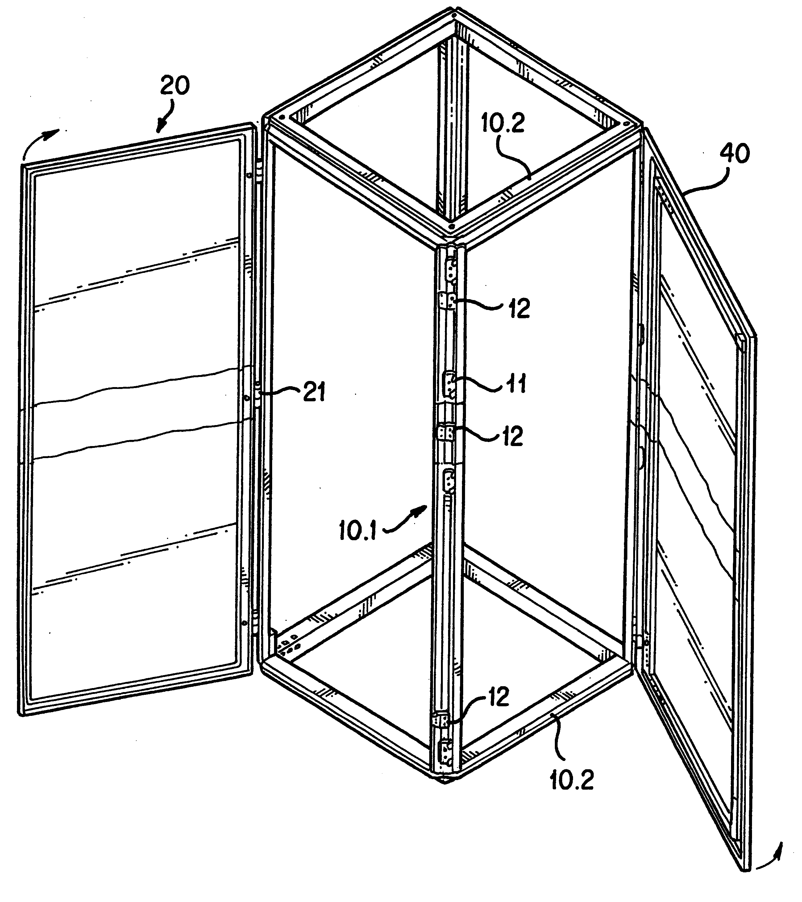
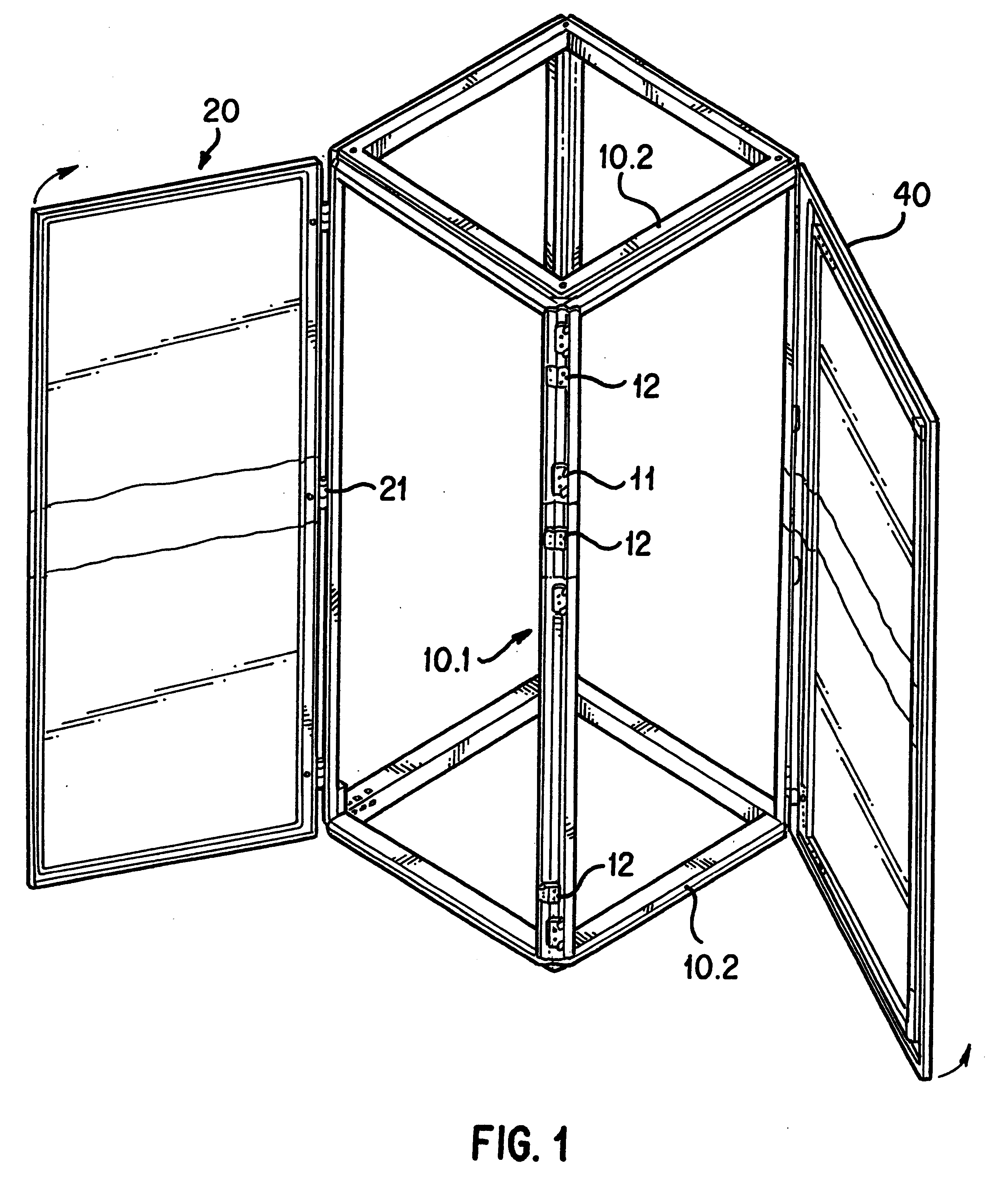
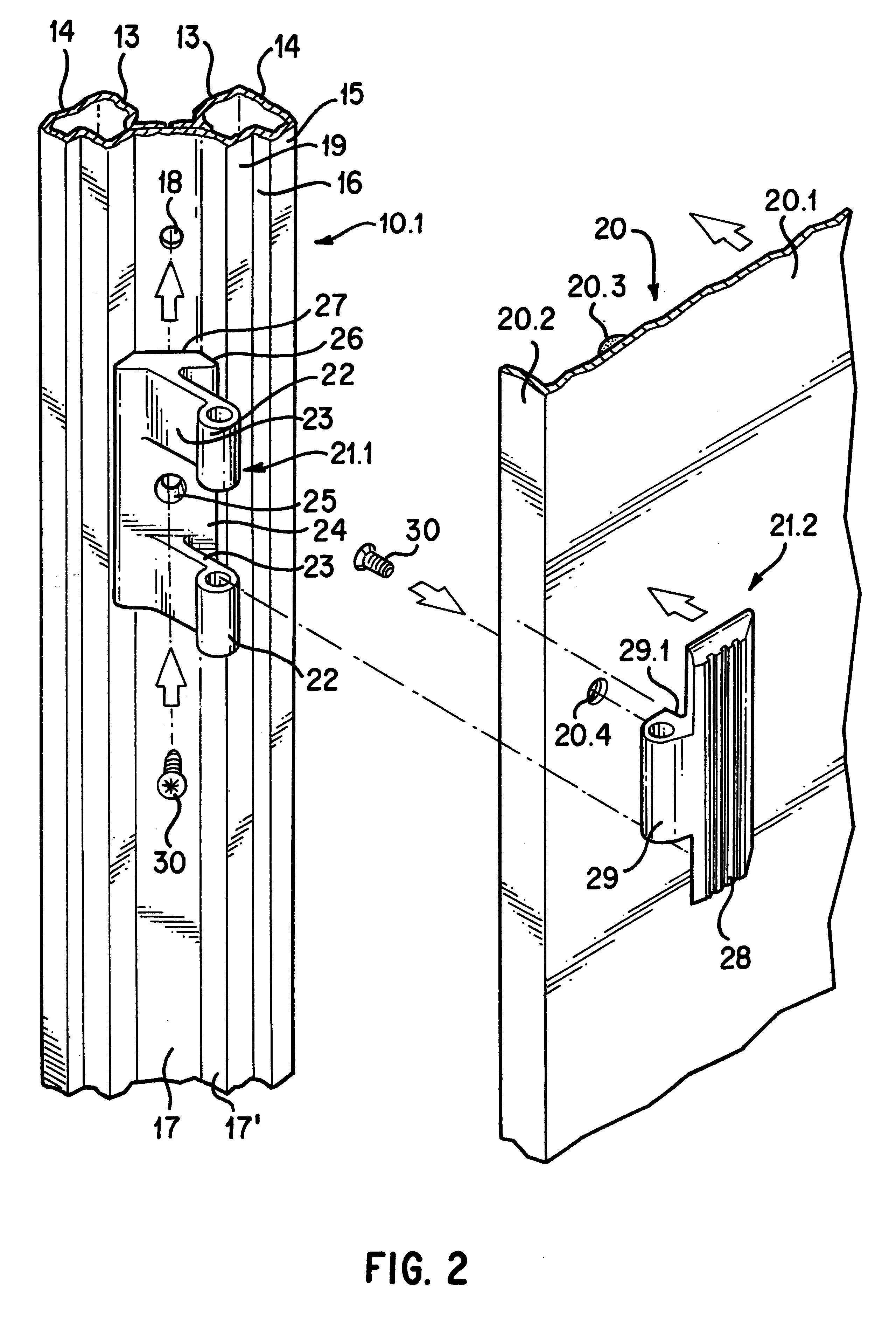
A rack of a switching cabinet is shown in FIG. 1. The rack comprises 12 frame sections; four vertical frame sections 10.1 and eight horizontal frame sections 10.2. The vertical frame sections 10.1 all have the same cross-sectional geometry. The horizontal frame sections 10.2 are designed as depth and width struts and have the same cross section. The open front side of the rack can be closed by means of a cabinet door 40. The cabinet door 40 is connected via hinges to one of the two vertical frame sections 10.1 on the front. The other vertical frame section 10.1 on the front is equipped with closure elements 11. The cabinet door 40 can be locked to the closure elements in the closed state. The three open sides of the rack can be covered with side walls 20. The side walls 20 can be fixedly screwed to the rack or designed as additional doors that are connected to pivot via hinges 21 on a vertical frame section 10.1. The side wall supports 12 are used to fix the side wall 20 in the clos...


PUM


Abstract

A switching cabinet with a rack assembled from horizontal and vertical frame sections, in which a switching cabinet body enclosed by the rack is covered by a cabinet door and side walls, the cabinet door being hinged around one of the vertical frame sections and pivotal about the vertical pivot axis. To obtain improved access to the interior of the switching cabinet, at least one of the side walls is fixedly mounted on the rack or is hinged to pivot about a vertical axis.

Description

1. Field of the InventionThis invention relates to a switching cabinet with a rack assembled from horizontal and vertical frame sections, in which the switching cabinet body enclosed by the rack can be covered with a cabinet door and side walls, the cabinet door being hinged to one of the vertical frame sections and is pivotal about a vertical pivot axis.2. Description of Prior ArtThis type of switching cabinet is known from German Patent Reference DE 41 03 785 C2.An interior space of such switching cabinets is equipped with electrical switching units. During operating time the electrical switching units must be maintained and replaced when necessary. The switching cabinets are often tightly occupied so that the accessibility to individual units is highly limited.It is one object of this invention to provide a switching cabinet of the type mentioned at the outset in which the accessibility to the switching cabinet interior is improved in simple fashion.The object of this invention i...

Claims


Application Information

Patent Timeline
Patent Type & Authority Patents(United States)
IPC IPC(8): E05D5/02E05D5/00H02B1/38H02B1/00E05D5/06H02B1/30
CPCE05D5/023H02B1/38E05D5/06E05Y2900/208
Inventor KOHLER, MARTINAREUTER, WOLFGANGBENNER, ROLF
Owner RITTALWERK RUDOLF LOH GMBH & CO KG
Why Eureka
Try Eureka