Selective zonal isolation within a slotted liner

Inactive Publication Date: 2001-07-03
SHELL OIL CO
View PDF14 Cites 167 Cited by
  • Summary
  • Abstract
  • Description
  • Claims
  • Application Information

AI Technical Summary

Problems solved by technology

However, different problems arise when the wellbore has been completed with the insertion of a known slotted liner.
Slotted l

Method used


Image

  • Selective zonal isolation within a slotted liner
  • Selective zonal isolation within a slotted liner
  • Selective zonal isolation within a slotted liner

Examples


Embodiment Construction

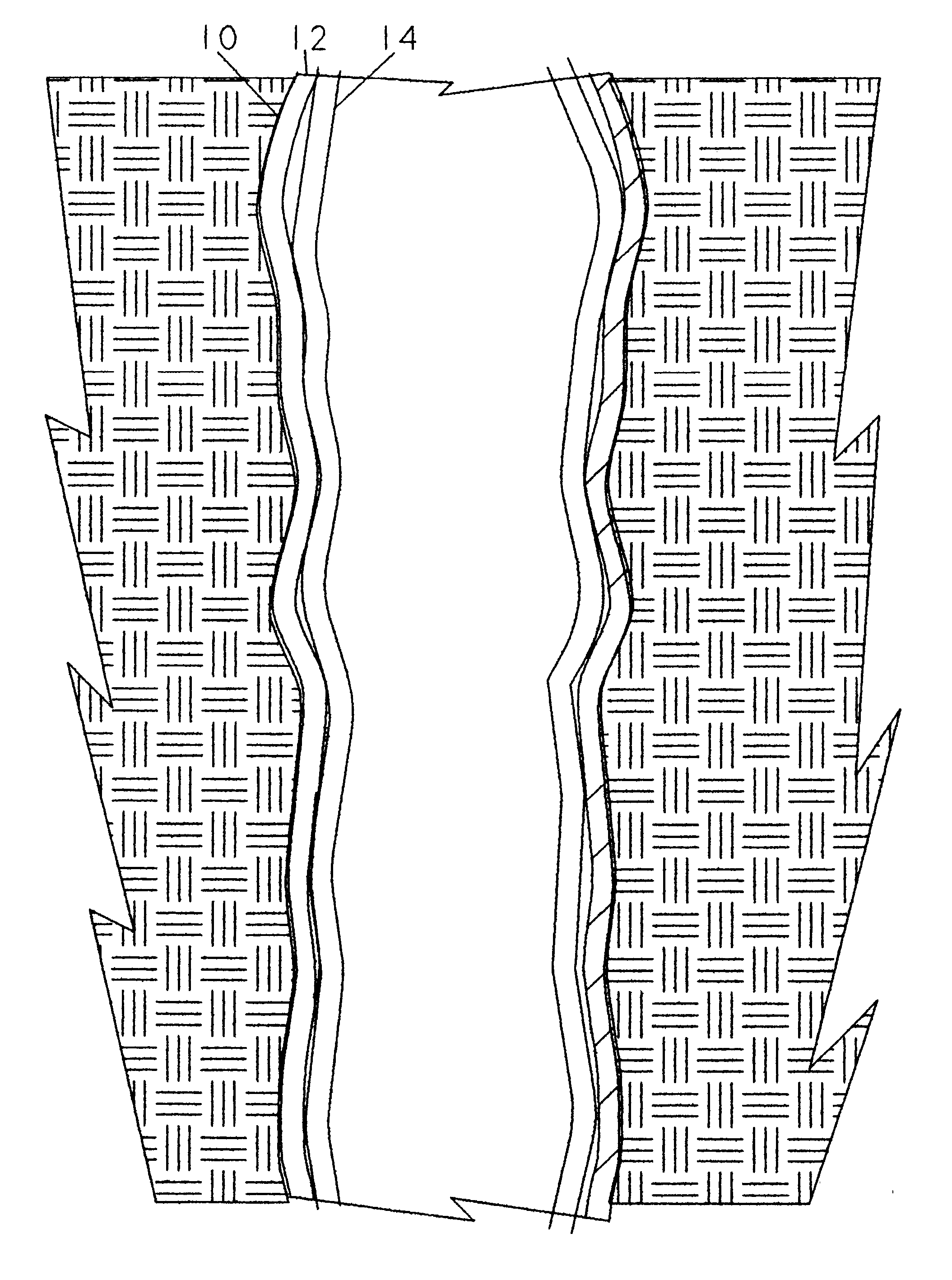
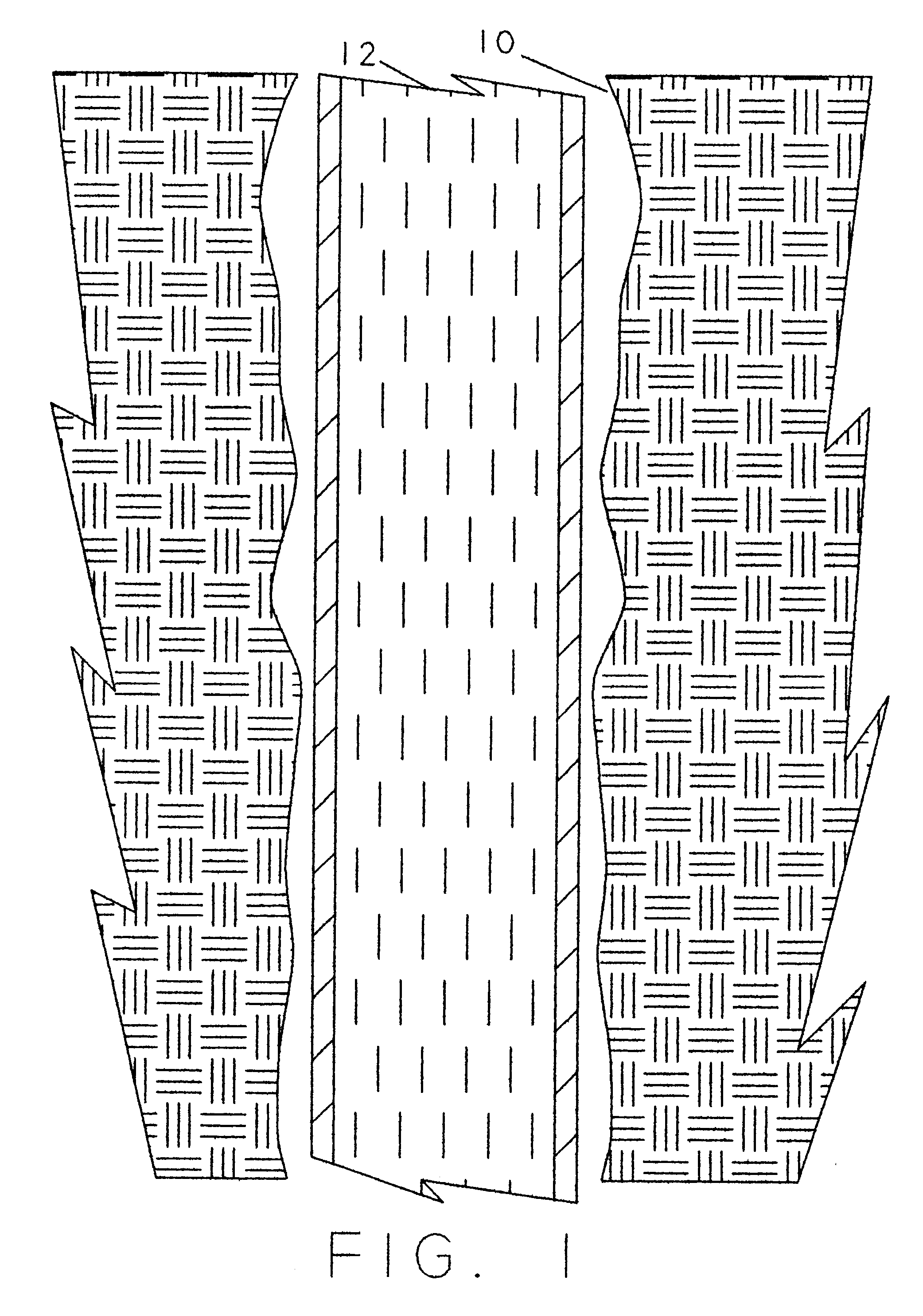
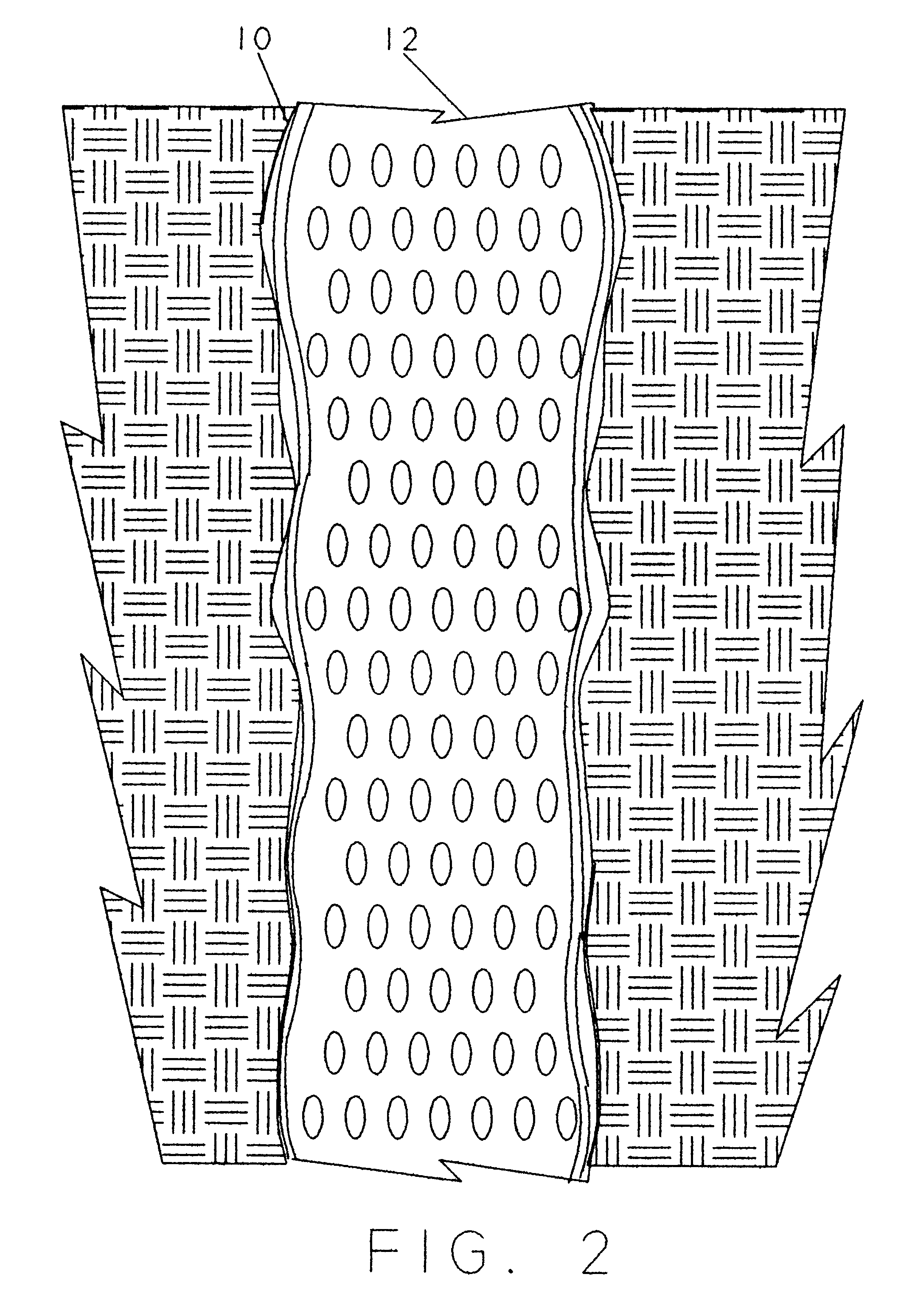
The wellbore 10 (FIGS. 1 and 2) has a first expandable liner 12 in place and running through a zone of the wellbore to be isolated. Generally this first liner, when expanded, does not fully contact all surfaces of the wellbore and it can contain a number of tares and / or rents in the slots. A second liner 14 (FIGS. 3 and 4) is inserted into the wellbore and positioned to cover at least the zone of the wellbore 10 to be isolated. Then the second liner 14 is expanded to sealing engage the first expanded slotted liner 12 sealing the openings therein to isolate that portion of the wellbore. This sealing can be improved by the addition of sealing materials (not shown), such as epoxies, rubber and the like.

While only a single second liner 14 has been shown, it is within the scope of the present invention to include insertion of more than one second liner. It is also within the scope of the invention that these second liners have physical characteristics different from one another so that, ...


PUM


Abstract

Selective isolation of a zone within a slotted liner completion of a wellbore is accomplished by expanding the original slotted liner to the full inner diameter of the wellbore into the annular area normally found around slotted liners. At least one solid tubular is run into the expanded area of the slotted liner and expanded at least in that section of the wellbore to be isolated. A custom expandable slotted liner can be run and expanded within the existing expanded slotted liner if excessive splits or rips should occur in the existing slotted liner due to expansion. Epoxies, rubber, or other sealing materials can also be utilized to better effect a seal between the liners.

Description

1. The Field of the InventionThe present invention relates to a method to provide isolation within a zone of a wellbore lined with a slotted liner by placing an expandable liner within the zone to be isolated.2. The Prior ArtThere is a great deal of prior art relating to isolating portions of a wellbore for various reason. For example, a zone may be producing water or gas and needs to be shut off for more effective production of the petroleum being recovered. Also, a zone may be producing sand or collapsing and creating debris and needs to be isolated to maintain and efficient operation. However, different problems arise when the wellbore has been completed with the insertion of a known slotted liner.One example of the prior art is U.S. Pat. No. 5,366,012 which describes a method of completing uncased sections of a wellbore by placing, at a predetermined position in the wellbore, a liner which is provided with a plurality of overlapping slots. The upper end of the liner is fixed in ...

Claims


Application Information

Patent Timeline
IPC IPC(8): E21B43/08E21B43/10E21B43/02E21B33/13
CPCE21B43/086E21B43/108E21B43/103
Inventor NAZZAI, GREGORY RICHARDFRANK, TIMOTHY JOHNCOON, ROBERT JOE
Owner SHELL OIL CO
Why Eureka
Try Eureka