Spring cushioned shoe

a cushioning shoe and spring technology, applied in the field of spring cushioning shoes, can solve the problems of injuring the lower back and all rotating joints of the leg, prone to extreme mechanical stress in the ball and heel area, and causing great shock to the body

Inactive Publication Date: 2001-09-04
SPIRA INC
View PDF26 Cites 149 Cited by
  • Summary
  • Abstract
  • Description
  • Claims
  • Application Information

AI Technical Summary

Problems solved by technology

When participating in sports, especially high impact sports such as volleyball and basketball, the foot of the participant; specifically the ball and heel areas are prone to extreme mechanical stress due to the force that will be imparted when the foot strikes a relative incompressible s

Method used


Image

  • Spring cushioned shoe
  • Spring cushioned shoe
  • Spring cushioned shoe

Examples


Embodiment Construction

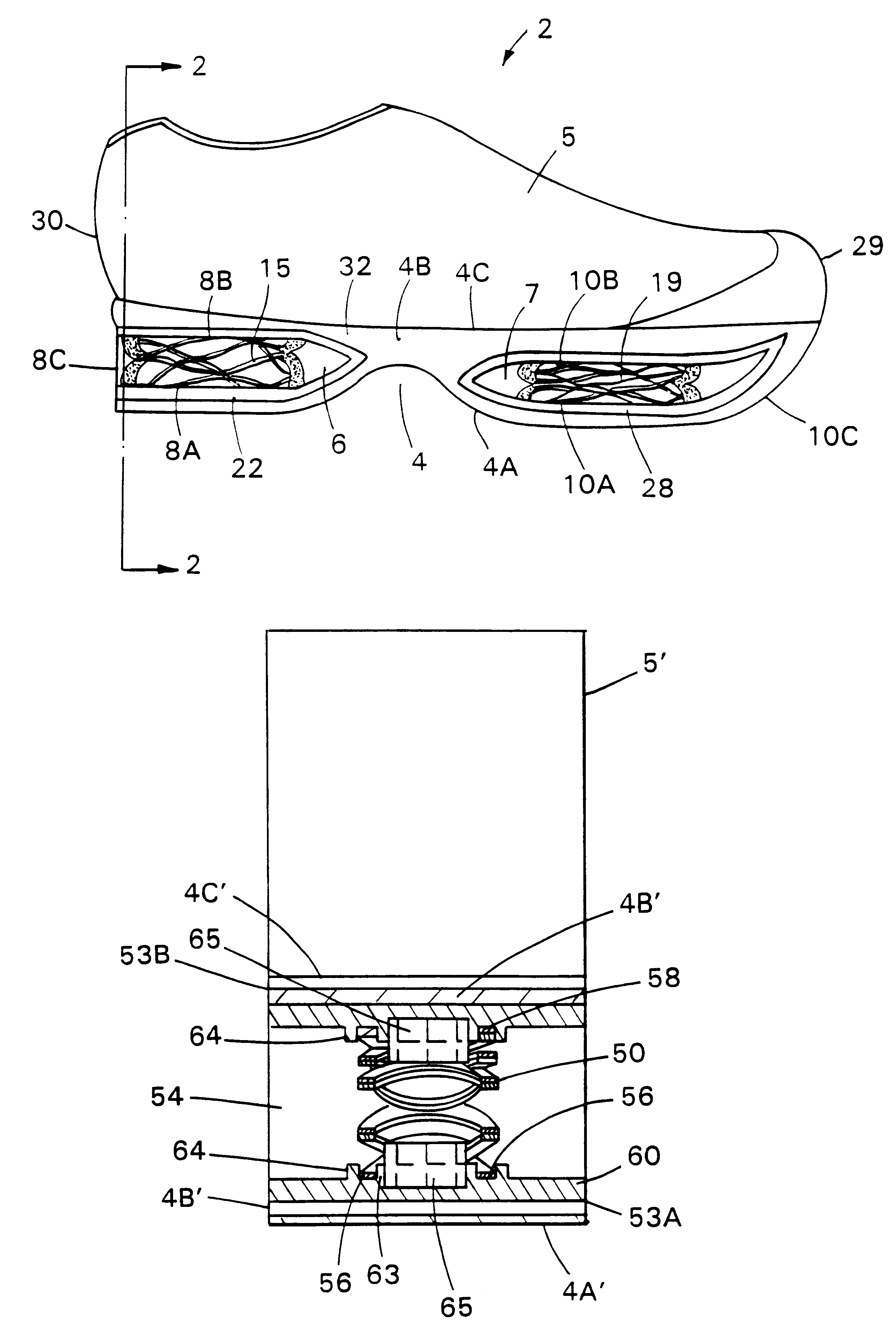
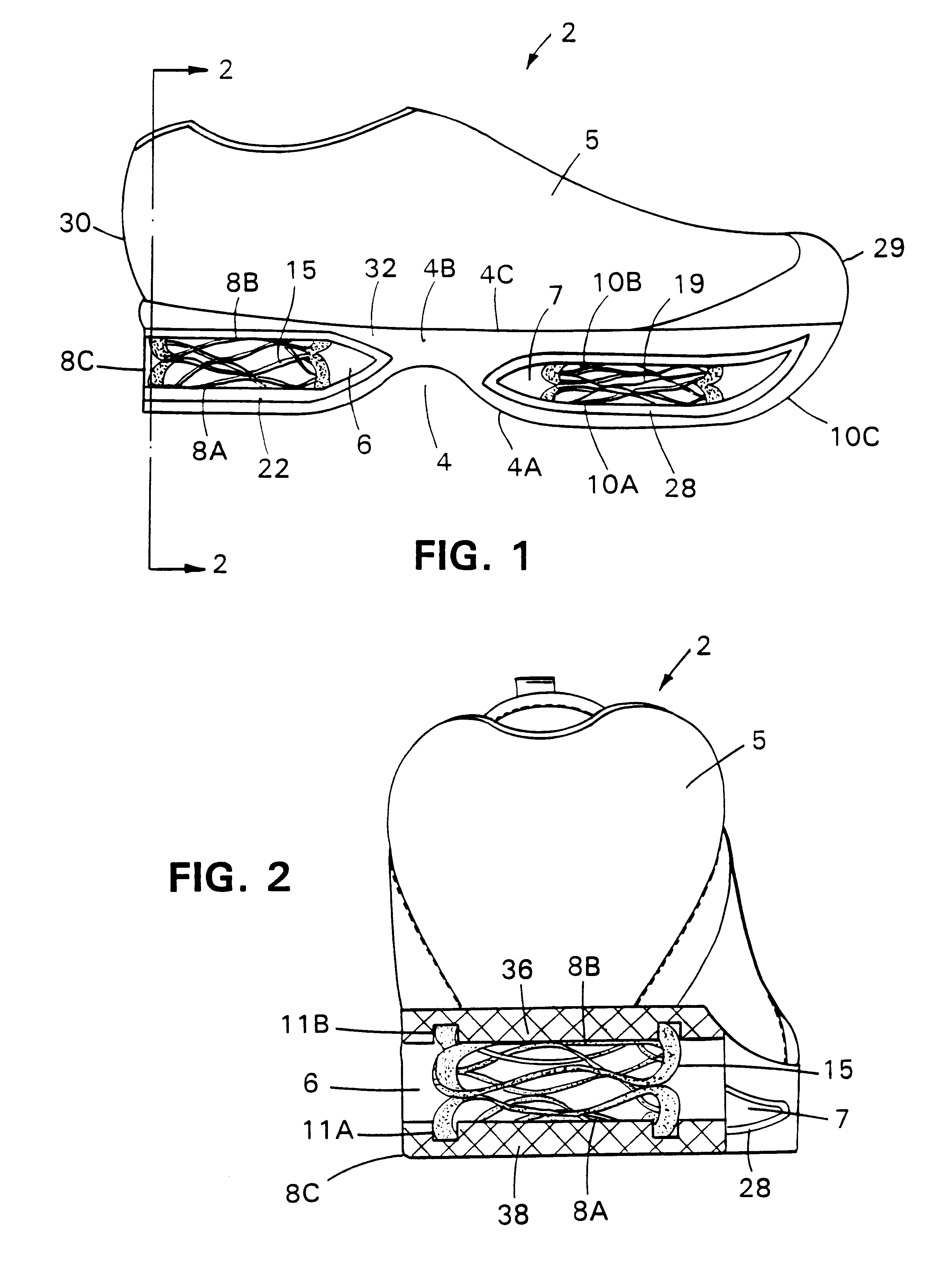
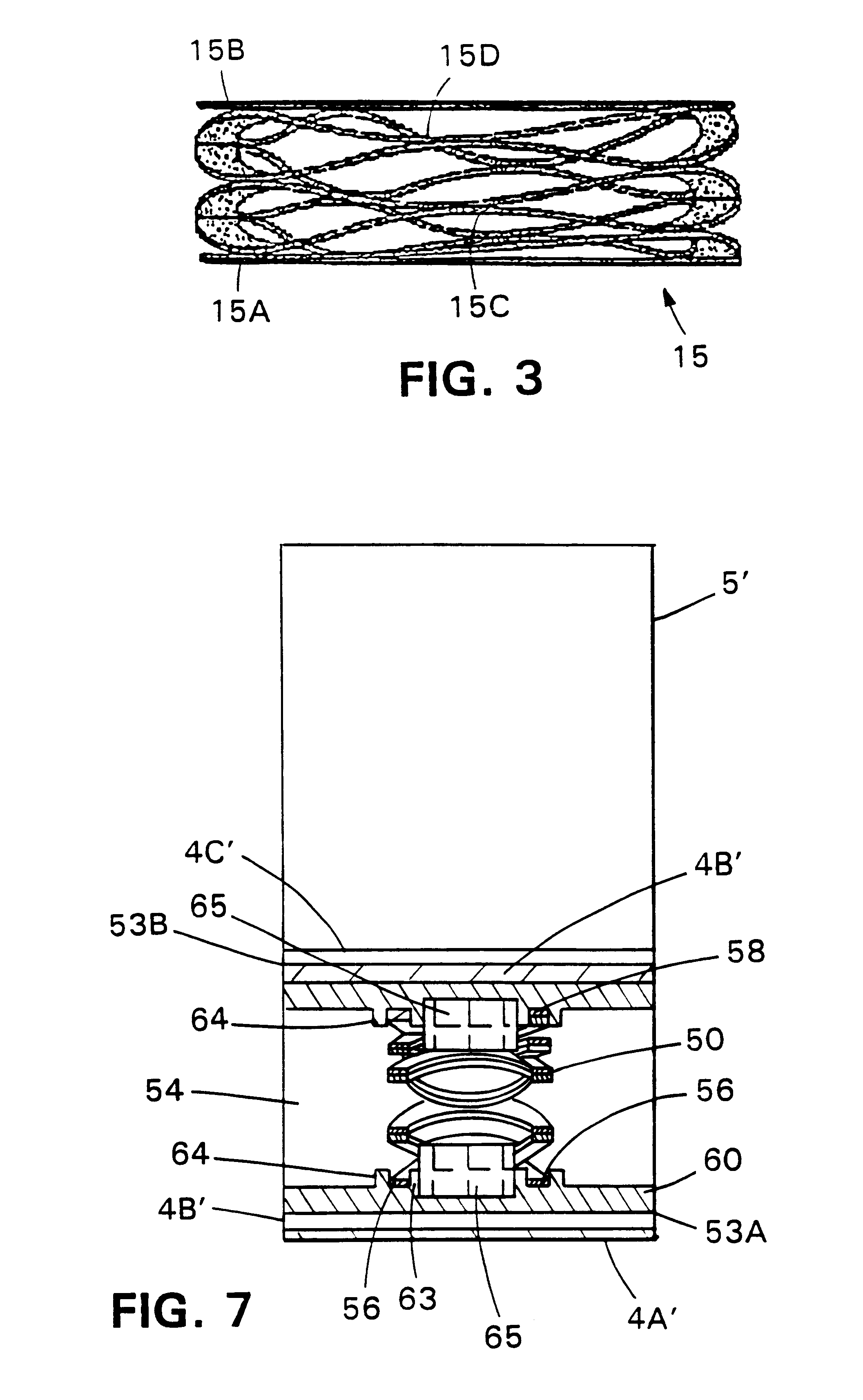
This invention relates to the use of ordinary compression springs as an integral part of shoes to cushion the impact of foot strikes and to provide recuperative energy return to the wearer. A spring-cushioned shoe incorporating the various features of the present invention is illustrated generally at 2 in FIGS. 1 and 2. The spring-cushioned shoe 2 shall hereafter be referred to as SCS 2.

The SCS 2 in FIG. 1 comprises: an upper shoe portion 5 firmly attached to shoe sole assembly 4. The shoe sole assembly 4 includes an outer sole 4A with first and second surfaces; middle sole 4B having first and second surfaces positioned such that its first surface is adhesively attached to the second surface of outer sole 4A; and, inner sole 4C whose first surface is adhesively attached to the second surface of middle sole 4B and whose second surface is in working contact with the lower region of upper shoe portion 5. In the present invention, the middle sole 4B is composed of foamed polymeric mater...


PUM


Abstract

A spring cushioned shoe is disclosed. The shoe includes a sole assembly that has a first spring disposed within a vacuity in the heel portion of the assembly, and a second spring disposed within a vacuity in the ball portion of the assembly. The springs are, e.g., wave springs that extend vertically from the upper to the lower internal boundaries of the vacuities.

Description

1. Technical FieldThis invention relates to the use of wave springs to cushion a shoe. Wave springs allow for reduced impact on the user during foot strike, thus increasing comfort and decreasing injury. Also, the wave springs will return a portion of the impact energy to the user for more efficient jumping, walking and / or running.2. Background ArtPeople involved in normal exercise programs are always seeking new equipment that can minimize the risk of injury to parts of the body caused by stress due to a foot strike. Athletes are also continually looking for ways to improve their performance levels in a variety of athletic and aerobic events that involve walking, running, or jumping while at the same time, taking steps to reduce the wear and tear attendant to the pounding endured by joints and bones. This can be achieved to some degree by the use of improved sporting equipment and more specifically improved shoes for both athletes and non-athletes.When participating in sports, espe...

Claims


Application Information

Patent Timeline
IPC IPC(8): A43B13/18A43B21/30
CPCA43B7/1425A43B13/183A43B7/144
Inventor KRAFSUR, DAVID S.LEVERT, FRANCIS E.
Owner SPIRA INC
Why Eureka
Try Eureka